COMBITHERM GAS INSTALLATION AND MAINTENANCE MANUAL — 6470ML
PG. 9
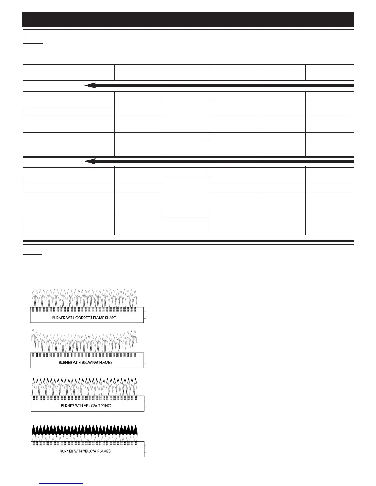
1.19 GAS FLAME PATTERNS
When starting the oven after initial installation, the gas lines must be free of air. It may take up to 30 minutes
to eliminate all air from the lines. If, after this time there is no pilot, call for factory assistance.
After the installation is complete, the oven must be test fired to
ensure that the system is operating properly. Follow the operating
instructions located in the cooking guide furnished with the oven.
Under most circumstances, initial operation will be the only
installer check necessary.
The flame pattern under both hot and cold conditions should be
stable on all burner ports. There should be no lifting or blowing
after 15 seconds of operation. Gas Combitherm ovens are not
equipped with air shutter adjustment on the burners. If the flame
pattern does not match correct pattern shown, contact the factory
for further directions.
Make certain the electric igniter lights the pilot burner quickly. The
main burner should light within 4 seconds, without problems and
should light smoothly with no harsh noise. When the oven is COLD,
cycle the oven ON and OFF five times to verify proper operation.
Allow the oven to heat for 5 minutes and repeat the process.
Check the flame pattern on the burners. The flames should be blue
in color with little or no yellow in the flame. Some yellow tipping
is normal with propane gas models, however, there should be no
indication any yellow tipping will produce soot on the combustion
chamber walls, pilot, or main burner.
COMBITHERM® GAS INSTALLATION
1.18 GAS PRESSURE CHART
The gas valve, pilot burner and nozzles for the main burner have been fitted according to the gas
type specified on the name plate. Technical specifications for the gas system are as follows:
Combitherm 6•10 7•14 10•10 10•20 20•20
ML Gas Model 12•18
Natural Gas
Connected pressure rating 7 in. W.C. 7 in. W.C. 7 in. W.C. 7 in. W.C. 7 in. W.C.
Min. connected pressure 5 in. W.C. 5 in. W.C. 5 in. W.C. 5 in. W.C. 5 in. W.C.
Max. connected pressure 14 in. W.C. 14 in. W.C. 14 in. W.C. 14 in. W.C. 14 in. W.C.
Nozzle pilot burner —————
Nozzle burner 220 320 280 400 400
Manifold pressure 3.5 in. W.C. 3.5 in. W.C. 3.5 in. W.C. 3.5 in. W.C. 3.5 in. W.C.
Gas Consumption 45 cu.ft/hr 81.9 cu.ft/hr 67 cu.ft/hr 112 cu.ft/hr 168.1 cu.ft/hr
Gross thermal output 45,500 Btu/hr 82,000 Btu/hr 68,000 Btu/hr 113,000 Btu/hr 170,000 Btu/hr
Propane Gas
Connected pressure rating 11 in. W.C. 11 in. W.C. 11 in. W.C. 11 in. W.C. 11 in. W.C.
Min. connected pressure 11 in. W.C. 11 in. W.C. 11 in. W.C. 11 in. W.C. 11 in. W.C.
Max. connected pressure 14 in. W.C. 14 in. W.C. 14 in. W.C. 14 in. W.C. 14 in. W.C.
Nozzle pilot burner
—————
Nozzle burner 135 190 170 220 220
Manifold pressure 10 in. W.C. 10 in. W.C. 10 in. W.C. 10 in. W.C. 10 in. W.C.
Gas Consumption 17.7 cu.ft/hr 32.9 cu.ft/hr 26.5 cu.ft/hr 44.1 cu.ft/hr 66.5 cu.ft/hr
Gross thermal output 45,500 Btu/hr 82,000 Btu/hr 68,000 Btu/hr 113,000 Btu/hr 170,000 Btu/hr
 Loading...