Do you have a question about the Alto-Shaam Vector Series and is the answer not in the manual?
Contact information for 24/7 emergency repair service provided by Alto-Shaam.
Explains the meaning and importance of signal words used in the manual.
Lists essential safety precautions for operating and maintaining the appliance.
Details required operator training and qualifications for using the appliance.
Specifies conditions for operation and guidelines for authorized service and repairs.
Specifies personal protective equipment required for cleaning and maintenance.
Outlines the knowledge and standards required for service technicians.
Step-by-step guide on how to power the oven on and off.
Procedure for updating the oven's interface board firmware via USB.
Procedure for updating the oven's control board firmware via USB.
Instructions for loading configuration files to set up the oven menu.
Diagram showing numbering for oven chambers for component identification.
Identifies components located on the front panel of the oven.
Identifies components and connections on the back panel of the oven.
Shows access panels and the components they provide access to.
Diagram and list identifying electrical components within the H4 model.
Diagram and list identifying electrical components within the H3 model.
Diagram and list identifying electrical components within the H2 model.
Details the function and operation of the check fans indicator light switch.
Illustrates terminal blocks for electrical supply connections for Non-CE and CE models.
Diagrams and description of the main disconnect switch for CE and standard models.
Illustrates circuit breakers for heating elements in H4, H3, and H2 models.
Description and diagrams of the VFD used for motor speed control.
Explains the function of SSRs for heater element control and provides connection details.
Details the line filter used in CE models, including capacitance and tolerance.
Explains the function of the 12VAC transformer and its voltage signal to the control board.
Describes the 12VDC power supply and its role in providing DC voltage to the control board.
Illustrates terminal blocks used for VFD and cooling fan connections.
Diagram and list identifying components and connectors on the interface board.
Detailed diagram and list of all connectors and components on the control board.
Diagrams and descriptions of relays used in the oven, including their functions and coils.
Specifies the type and rating of fuses used for chamber lights.
Details the specifications of the Wye filter used in CE models.
Illustrates the control circuit breakers and their labeling.
Describes the resettable high limit switches, their contacts, and temperature rating.
Diagrams and identifies components on the left service panel.
Details specific components found on the left service panel.
Details the specifications for chamber air temperature probes.
Details the speaker impedance (8 Ohms).
Explains door switch states (closed/open) and associated voltage readings.
Diagrams and identifies components on the right service panel.
Details specific components found on the right service panel.
Diagram of the cooling air filter.
Identifies internal components of the oven.
Provides details on internal components like chamber lights and filters.
Describes the oven's state when powered on but not actively cooking or preheating.
Describes the oven's state when powered on and the display is illuminated.
Explains the oven's operation during the preheat cycle, including fan speeds.
Describes the oven's state after reaching setpoint, during temperature stabilization.
Explains the oven's operation during the cooking cycle, including door interaction.
Describes the oven's status and alerts at the end of the cooking cycle.
Explains the rapid ON/OFF state based on chamber temperature deviations.
Describes the oven's operation during the cool down process, including fan speeds.
Describes the oven's transition to OFF state after completing cool down.
Lists requirements and conditions before performing maintenance tasks.
Outlines daily cleaning and checks for the oven.
Outlines weekly cleaning procedures for the oven.
Outlines monthly inspection and cleaning of filters.
Lists annual checks, tightening, testing, and recording tasks.
Safety warnings and precautions before starting the oven cleaning process.
Step-by-step guide for daily cleaning of the oven exterior and spills.
Step-by-step guide for weekly cleaning, including stainless steel polish and interior cleaner.
Step-by-step guide for monthly cleaning of cooking racks and jet plates.
Instructions for removing, cleaning, and re-installing oven filters.
Step-by-step guide to test the functionality of the oven's cooling fans.
Procedure to test the oven's blower motors, including setting air speed.
Guide to test oven heaters, including measuring amp draw and checking operation.
Steps to calibrate chamber thermocouples for accurate temperature readings.
Lists common error messages, their meanings, and required actions.
Diagnostic steps to troubleshoot why the oven is not powering on.
Steps to troubleshoot the oven screen failing to turn on.
Troubleshooting for issues with the oven not powering down or entering cool down.
Steps to resolve a solid white display on the oven screen.
Troubleshooting for a touchscreen that is unresponsive or gives incorrect responses.
Troubleshooting steps when the screen shows icons but no text.
Troubleshooting for a persistent striped screen lock on the oven display.
Diagnoses why chambers are not heating due to missing SSR control voltage.
Troubleshooting when chambers don't heat due to heater element line voltage issues.
Diagnoses why a chamber is heating up slowly.
Troubleshooting steps when one chamber's blower fan is not operating.
Troubleshooting when all chamber blower fans fail to operate.
Steps to troubleshoot why chamber lights are not illuminating.
Troubleshooting steps when the check fan indicator light is on.
Diagnostic steps for when the cooling fans are not operating.
Step-by-step guide for removing and installing the blower motor.
Instructions for removing and installing a heater element in the oven.
| Category | Oven |
|---|---|
| Manufacturer | Alto-Shaam |
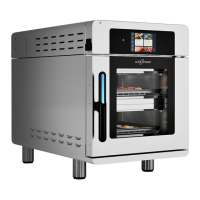
| Series | Vector Series |
| Type | Multi-Cook Oven |
| Construction | Stainless steel |
| Dimensions | Varies by model |
| Weight | Varies by model |
| Power Source | Electric |
| Power Supply | 208-240V |