COMPONENTS
Ve ct or™ H Se ries ▪ S ervice Ma nual ▪ MN -4 6 54 3 ▪ R ev 01 ▪ 11/ 19
35
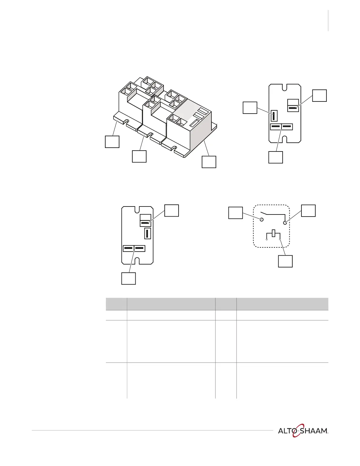
Relays
Ref. Description Ref. Description
1 RL-3 (H3 only) 4 Common terminal
2 RL-1, T9C, 240VAC coil
Input to the control board for the
check fan indicator light
Coil—10.90 K Ohm
5 Coil terminal
3 RL-2, AZ 22, 12VDC coil
Blowers/fan
Coil—155 Ohm
6 Normally open terminal
VMC-PHD-001951
T9C
T9C
AZ 22
T9C
AZ 22
5
4
3
1
2
6
6
5
4
6
5
 Loading...