www.altronicinc.com
3
ALTRONIC CD200 IGNITION SYSTEM
4.0 IGNITION COILS
4.1
USE ONLY THE ALTRONIC COILS INDICATED HERE:
•
UNSHIELDED: 501061, 591010, 591040
•
FLANGE: 591012, 591018
•
SHIELDED: 501061-S, 591010-S
•
INTEGRAL: 591007, 591011A, 591011B
4.2
Mount the ignition coils as close to the spark plugs as possible keep-
ing the high-tension lead length to a minimum but also keeping
temperatures below 200°F. (95°C.) during operation.
5.0 PRIMARY WIRING
5.1
The CD200 system requires a battery or other DC power source
providing 12-28 Vdc for running and a minimum of 8 volts for en-
gine starting. Refer to FIG. 3 for details of the connection to the DC
power source.
5.2
Primary wiring hookup is shown in the wiring diagrams – FIGS. 5
THROUGH 11.
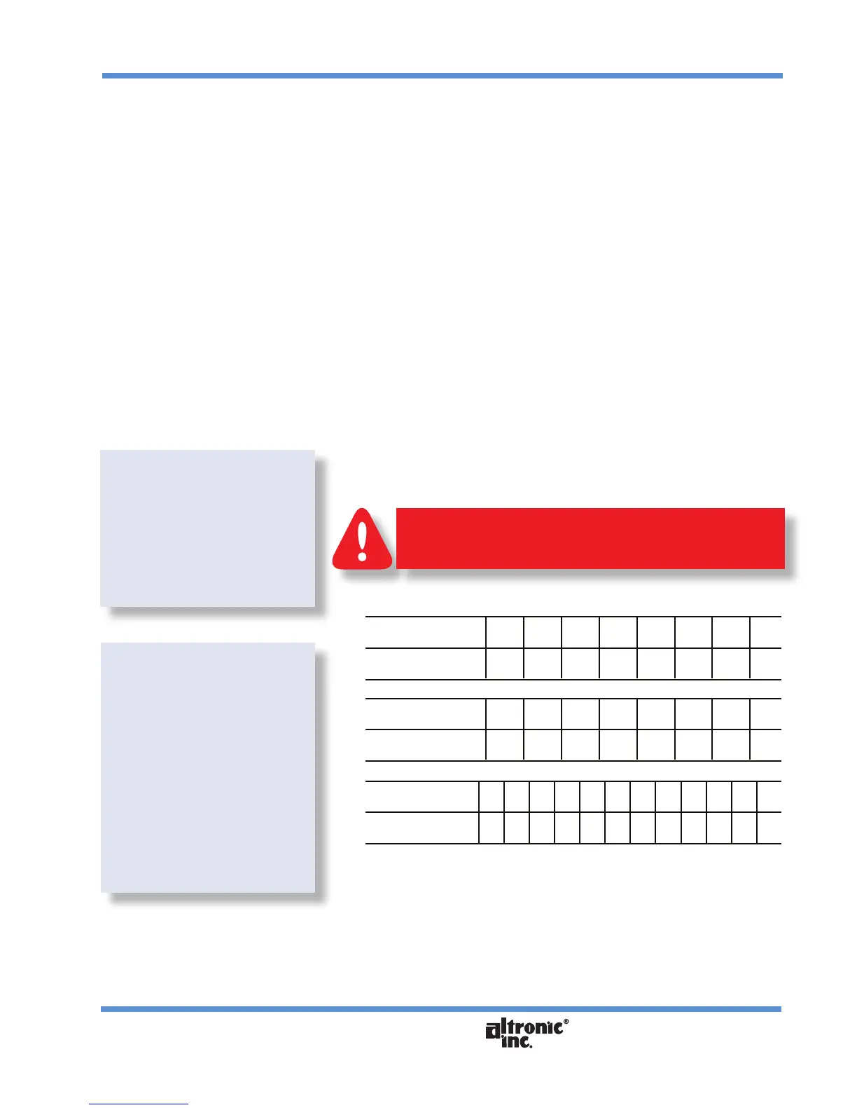
Usethetablesbelowtorecordtheactualringorderandwiring.
791070-6, 791070-8* A B C D E F H* K*
ENGINE CYL. NO.
791080-6, 791080-8* A B C D E F H* I*
ENGINE CYL. NO.
791070-12 A1 A2 B1 B2 C1 C2 D1 D2 E1 E2 F1 F2
ENGINE CYL. NO.
The common coil ground lead on -6 and -8 units is the J harness
lead. On -12 units, the common coil ground leads are J1 and H2.
WIRING DIAGRAMS:
FIG. 5 — 4-CYLINDER
FIG. 6 — 6-CYLINDER
FIG. 7 — 8-CYLINDER
FIGS. 8–11 — 12-CYLINDER
NOTE: With unit 791070-12,
follow FIG. 10 if the rst
engine ring angle is 60
degrees or less (for example,
30°–90°). Use FIG. 11 if the
rst engine ring angle is
greater than 60 degrees
(for example, 90°–30°).
See section 9.20 for pro-
gramming the slave ring
angle with unit 791070-12.
THE HOOKUP SHOWN IS FOR THE MOST COMMON ENGINE
FIRING ORDER. CONNECT TO THE IGNITION COILS ACCORD-
ING TO THE ACTUAL ENGINE FIRING ORDER.
WARNING: