www.altronicinc.com
9
ALTRONIC CD200 IGNITION SYSTEM
9.18
ENERGY FLAGS:
Select one of four output energy settings for the CD200:
Bit 1 OFF Bit 0 OFF Vcap = 150 volts
Bit 1 OFF Bit 0 ON Vcap = 160 volts
Bit 1 ON Bit 0 OFF Vcap = 170 volts
Bit 1 ON Bit 0 ON Vcap = 180 volts
Default setting is 160 volts at the capacitor. This voltage can only be
measured using a device with an input impedance of 1 megaohm or
higher with no other device connected.
9.19
UNIT 791070-12 – ENABLE SLAVE FIRING FLAG:
WhenthisLEDstatusagisactivated,theignitionwillgeneratea
secondslaveringforeach(x+1)referencepulse.Fora(6+1)disc
pattern,theignitionwillre12outputswhenthisagisactivated,
and6outputswhenthisagisnotactivated.Modicationofthis
ag through the Terminal Program requires that the engine be
stoppedandtheG-leadbegrounded.
9.20
UNIT 791070-12 – SLAVE FIRING ANGLE SETTING:
Thisnumericentrycongurestheangleoftheslaveringrelative
tothestandardringsthataregeneratedforeach(x+1)reference
pulse.Entryrangeis25.0°to60.0°whichisusedtosettheslaver-
ing angle on a 12-cylinder, 4-cycle engine. The slave angle must be
thesmallerofthetwoanglesthatdenetheengineringpattern.
For example, ring patterns of either30°–90° or90°–30° would
requiretheslaveanglebeenteredas“30”.Modicationofthisvalue
through the Terminal Program requires that the engine be stopped
andtheG1leadbegrounded.
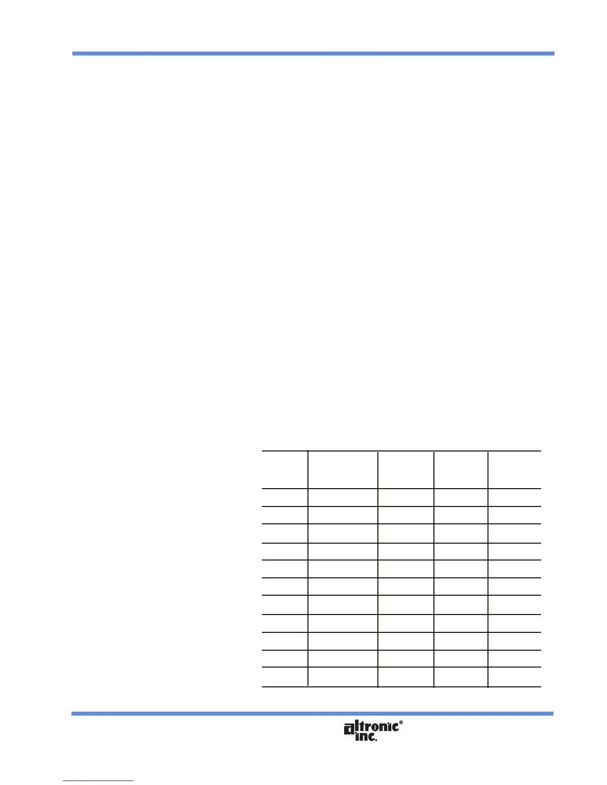
The following patterns are applications suitable for unit 791070-12:
ENGINE SECT. 9.4 SECT. 9.20
NO. FIRING DISC SLAVE WIRING
CYLS. ANGLE SETTING ANGLE DIAGRAM
8 60°–120° 4+1 60° FIG. 10
8 120°–60° 4+1 60° FIG. 11
10 54°–90° 5+1 54° FIG. 10
10 90°–54° 5+1 54° FIG. 11
12 30°–90° 6+1 30° FIG. 10
12 40°–80° 6+1 40° FIG. 10
12 50°–70° 6+1 50° FIG. 10
12 55°–65° 6+1 55° FIG. 10
12 60°–EVEN 6+1 60° FIG. 10
12 75°–45° 6+1 45° FIG. 11
12 90°–30° 6+1 30° FIG. 11