9
9 Ductwork
This air handler is designed for a complete supply and return
ductwork system.
To ensure correct system performance, the ductwork is to be sized
to accommodate 350-450 CFM per ton of cooling with the static
pressure not to exceed 0.5" in w.c. Refer to ACCA Manual D,
Manual S and Manual RS for information on duct sizing and appli-
cation. Flame retardant ductwork is to be used and sealed to the
unit in a manner that will prevent leakage.
NOTE: A downflow application with electric heat must have an L-
shaped sheet metal supply duct without any outlets or registers
located directly below the heater.
9.1 Return Ductwork
DO NOT LOCATE THE RETURN DUCTWORK IN AN AREA THAT
CAN INTRODUCE TOXIC, OR OBJECTIONABLE FUMES/
ODORS INTO THE DUCTWORK. The return ductwork is to
be connected to the air handler bottom (upflow configura-
tion).
10 Return Air Filters
Each installation must include a return air filter. This filtering may
be performed at the air handler using the factory filter rails or
externally such as a return air filter grille. When using the factory
filter rails, a nominal 16x20x1”, 20x20x1” or 24x20x1” (actual di-
mension must be less than 23-½”x20”) filter can be installed on a
B, C and D cabinet respectively (the cabinet size is the seventh
letter of the model number).
11 Electric Heat
Do not operate this product without all the ductwork
attached.
Refer to the installation manual provided with the electric heat kit
for the correct installation procedure. All electric heat must be
field installed. If installing this option, the ONLY heat kits that are
permitted to be used are the HKS series. Refer to the air handler
unit’s Serial and Rating plate or the HKS specification sheets to
determine the heat kits compatible with a given air handler. No
other accessory heat kit besides the HKS series may be installed in
these air handlers.
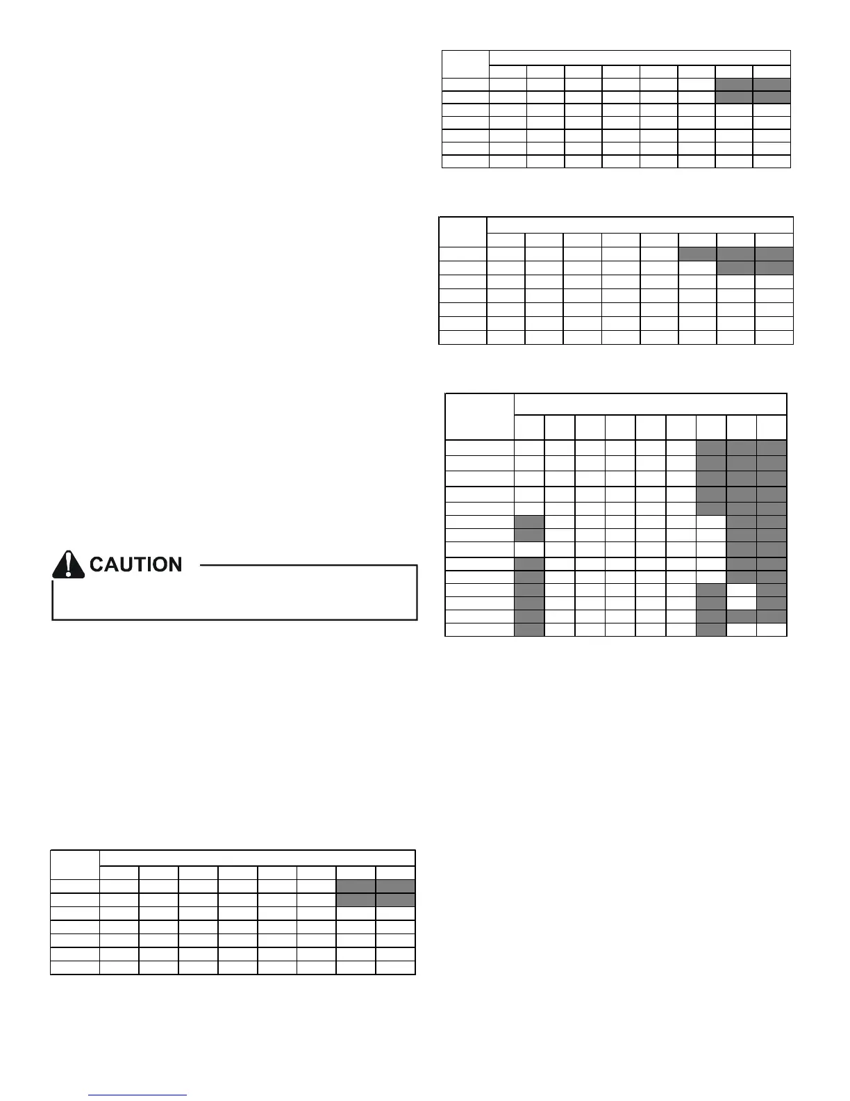
The heating mode temperature rise is dependent upon the sys-
tem airflow, the supply voltage, and the heat kit size (kW) selected.
Use data provided in Tables 3, 4 and 5 to determine the tempera-
ture rise (°F).
3 5 6 8 10 15 19/20 25
800 121923313756
1000 9 1519253044
1200 8 12152125374962
1400 7 11131821324253
1600 6 9 12 15 19 28 37 46
1800 5 8 10 14 16 25 33 41
2000 5 7 9 1215223037
CFM
HEAT KIT NOM INAL kW
230/1/60 SUPPLY VOLTAGE - TEMP. RISE °F
Table 2
3568101519/2025
800 111822303554
1000 9 1418242842
1200 7 12152024354759
1400 6 10131720304051
1600 6 9 11 15 18 27 35 44
1800 5 8 10 13 16 24 31 39
2000 4 7 9 12 14 21 28 35
CFM
HEAT KIT NOMINAL kW
220/1/60 SUPPLY VOLTAGE - TEMP. RISE °F
Table 3
3568101519/2025
800 1017212833
1000 8 1317222740
1200 7 11141922334556
1400 6 10121619293848
1600 5 8 10 14 17 25 33 42
1800 5 7 9 12 15 22 30 37
2000 4 7 8 11 13 20 27 33
CFM
HEAT KIT NOMINAL kW
208/1/60 SUPPLY VOLTAGE - TEMP. RISE °F
Table 4
3 5 6 8 10 15 19 20 25
AVPTC25B14 550 650 700 800 850 875
AVPTC29B14 550 650 700 800 875 875
AVPTC35B14 550 650 700 800 875 1050
AVPTC37B14 550 650 700 800 875 1050
AVPTC33C14 600 700 750 875 950 950
AVPTC39C14 850 900 1000 1170 1345
1345
AVPTC49C14 1170 1170 1170 1170 1345 1345
AVPTC31C14 600 850 900 1000 1170 1345 1345
AVPTC37C14 850 900 1000 1170 1345 1345
AVPTC59C14 1170 1170 1170 1170 1345 1345
AVPTC37D14 1240 1240 1240 1240 1520 1520
AVPTC59D14 1240 1240 1240 1240 1520 1520
AVPTC49D14 1250 1300 1500 1550 1720
AVPTC61D14 1250 1300 1500 1550 1780 1850 1850
Model
HEATER (kW)
MINIMUM CFM REQUIREMENTS FOR HEATER KITS
Table 5
NOTE: For installations not indicated above the following formula
is to be used:
TR = (kW x 3412) x (Voltage Correction) / (1.08 x CFM)
Where: TR = Temperature Rise
kW = Heater Kit Actual kW
3412 = Btu per kW
VC* = .96 (230 Supply Volts)
= .92 (220 Supply Volts)
= .87 (208 Supply Volts)
1.08 = Constant
CFM = Measured Airflow
VC* (Voltage Correction)
NOTE: The Temperature Rise Tables can also be used to estimate
the air handler airflow delivery. When using these tables for this
purpose set the room thermostat to maximum heat and allow the
system to reach steady state conditions. Insert two thermometers,
one in the return air and one in the supply air. The temperature
rise is the supply air temperature minus the return air temperature.
Using the temperature rise calculated, CFM can be estimated from
the TR formula above. See Spec Sheets and/or Service Manual for
more information.
 Loading...