SYSTEM OPERATION
12
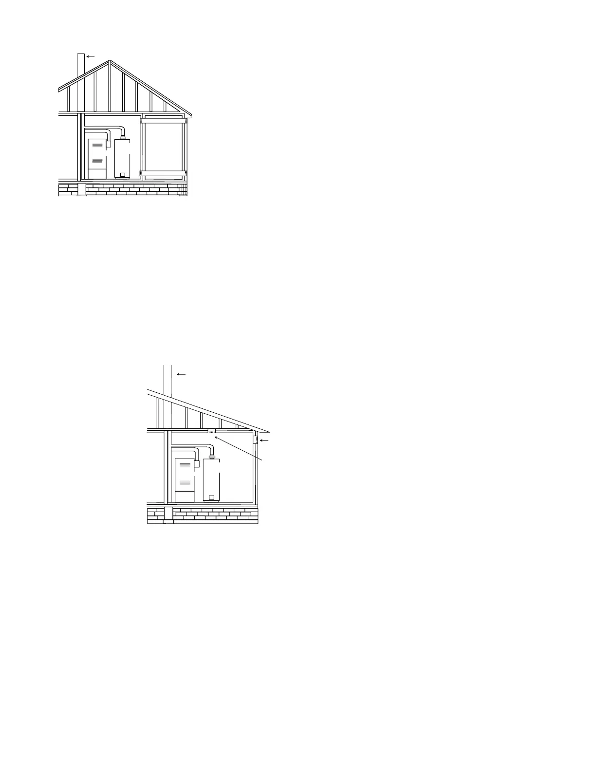
Furnace
Water
Heater
Chimney or Gas Vent
Outlet air duct
Inlet air duct
through Horizontal Ducts.
9.3.3.2* One Permanent Opening Method. One permanent openings,
commencingwithin12in.(300mm)ofthetopoftheenclosure,shallbe
provided.Theapplianceshallhaveclearancesofatleast1in.(25mm)from
thesidesandbackand6in.(150mm)fromthefrontoftheappliance.The
opening shall directly communicate with the outdoors or shall communicate
through a vertical or horizontal duct to the outdoors or spaces that freely
communicate with the outdoors (see Figure A.9.3.3.2) and shall have a
minimum free area of the following:
(1) 1in.
2
/3000 Btu/hr (700 mm
2
per kW) of the total input rating of all
appliances located in the enclosure, and
(2) Notlessthanthesumoftheareasofallventconnectorsinthespace.
Furnace
Water
Heater
Opening
Chimney or Gas Vent
Alternate
Opening
Location
From Outdoors through Single Combustion Air Opening.
9.3.4 Combination Indoor and Outdoor Combustion Air. The use of a
combination of indoor and outdoor combustion air shall be in accordance
with (1) through (3) (see example calculation in Annex J]:
(1) Indoor Openings: Where used, openings connecting the interior spaces
shallcomplywith9.3.2.3.
(2) Outdoor Opening(s) Location. Outdoor opening(s) shall be located in
accordancewith9.3.3.
(3) Outdoor Opening(s) Size. The outdoor opening(s) size shall be calcu-
lated in accordance with the following:
(a) The ratio of the interior spaces shall be the available volume of
allcommunicatingspacesdividedbytherequiredvolume.
(b) The outdoor size reduction factor shall be 1 minus the ratio of
interiorspaces.
(c) The minimum size of outdoor opening(s) shall be the full size
ofoutdooropening(s)calculatedinaccordancewith9.3.3,mul-
tipliedbythereductionfactor.Theminimumdimensionofair
openingsshallnotbelessthan3in.(80mm).
9.3.5 Engineered Installations. Engineered combustion air installations
shall provide an adequate supply of combustion, ventilation, and dilution
airandshallbeapprovedbytheauthorityhavingjurisdiction.
9.3.6 Mechanical Combustion Air Supply. Where all combustion air
is provided by a mechanical air supply system, the combustion air shall
besuppliedformoutdoorsattheminimumrateof0.35ft
3
/min per 1000
Btu/hr(0.034m
3
/minperkW)forallapplianceslocatedwithinthespace.
9.3.6.1 Where exhaust fans are installed, additional air shall be provided
toreplacetheexhaustedair.
9.3.6.2 Each of the appliances served shall be interlocked to the mechanical
air supply system to prevent main burner operation where the mechanical
airsupplysystemisnotinoperation.
9.3.6.3 Where combustion air is provided by the building’s mechanical
ventilationsystem,thesystemshallprovidethespeciedcombustionair
rateinadditiontotherequiredventilationair.
9.3.7 Louvers, Grilles, and Screens.
9.3.7.1 Louvers and Grilles. The required size of openings for combus-
tion, ventilation, and dilution air shall be based on the net free area of
eachopening.Wherethefreeareathroughadesignoflouverorgrilleor
screen is known, it shall be used in calculating the size opening required
toprovidethefreeareaspecied.Wherethelouverandgrilledesignand
free area are not known, it shall be assumed that wood louvers will have
25 percent free area, and metal louvers and grilles will have 75 percent free
area.Nonmotorizedlouversandgrillesshallbexedintheopenposition.
9.3.7.2 Minimum Scree Mesh Size. Screens shall not be smaller than
1/4in.mesh.
9.3.7.3 Motorized Louvers. Motorized louvers shall be interlocked with
the appliance so they are proven in the full open position prior to main
burnerignitionandduringmainburneroperation.Meansshallbeprovided
to prevent the main burner form igniting should the louver fail to open
during burner startup and to shut down the main burner if the louvers close
duringburneroperation.
9.3.8 Combustion Air Ducts. Combustion air ducts shall comply with
9.3.8.1through9.3.8.8.
9.3.8.1 Ducts shall be constructed of galvanized steel or a material having
equivalentcorrosionresistance,strength,andrigidity.
Exception: Within dwellings units, unobstructed stud and joist spaces shall
not be prohibited from conveying combustion air, provided that not more
than one reblock is removed.
9.3.8.2 Ducts shall terminate in an unobstructed space, allowing free
movementofcombustionairtotheappliances.
9.3.8.3 Ductsshallserveasinglespace.
9.3.8.4 Ducts shall not serve both upper and lower combustion air openings
wherebothsuchopeningsareused.Theseparationbetweenductsservicing
upper and lower combustion air openings shall be maintained to the source
ofcombustionair.
 Loading...