SYSTEM OPERATION
24
are identied as HUM and EAC. The humidier and electronic
air cleaner neutral terminals are identied as NEUTRAL. All eld
wiring must conform to applicable codes. Connections should be
made as shown. (See Figure 28.)
If it is necessary for the installer to supply additional line
voltage wiring to the inside of the furnace, the wiring must
conform to all local codes, and have a minimum temperature
rating of 105°C. All line voltage wire splices must be made
inside the furnace junction box.
The integrated control module single humidier terminal
(HUM) is energized with 115 volts whenever the induced
draft blower is energized. This terminal can also be used
to provide 115 volt power to a humidier transformer. The
remaining primary transformer wire would be connected to the
Line N on the control board. The integrated control module
electronic air cleaner terminals (EAC) are energized with 115
volts whenever the circulator blower is energized.
Wire routing must not to interfere with circulator blower
operation, lter removal, or routine maintenance.
WARNING
AVID E RISK ELECRICAL SCK INJR R DEA E
RNACE MS E ELECRICALL GRNDED IN ACCRDANCE WI LCAL
CDES R IN EIR ASENCE WI E LAES EDIIN E
N
AINAL
E
LECRIC
C
DE
WARNING
IG
VLAGE
D
ISCNNEC
ALL
PWER ERE SERVICING R
CANGING AN ELECRICAL WIRING
M
LIPLE PWER
SRCES MA E PRESEN
AILRE D S MA CASE
PRPER DAMAGE PERSNAL INJR R DEA
A 24 volt humidier can be connected to the normally open
terminal of the main pressure switch. The humidier common
would then be connected to “C” on the control board low
voltage terminal strip.
If it is necessary for the installer to supply additional line
voltage wiring to the inside of the furnace, the wiring must
conform to all local codes, and have a minimum temperature
rating of 105°C. All line voltage wire splices must be made
inside the furnace junction box.
Low voltage connections can be made through either
the right or left side panel. Wire routing must not interfere
with circulator blower operation, lter removal, or routine
maintenance.
A 40 V.A. transformer and an integrated electronic control are
built into the furnace to allow use with most cooling equipment.
Consult the wiring diagram, located in the Technical Manual
or on the blower door for further details of 115 Volt and 24
Volt wiring.
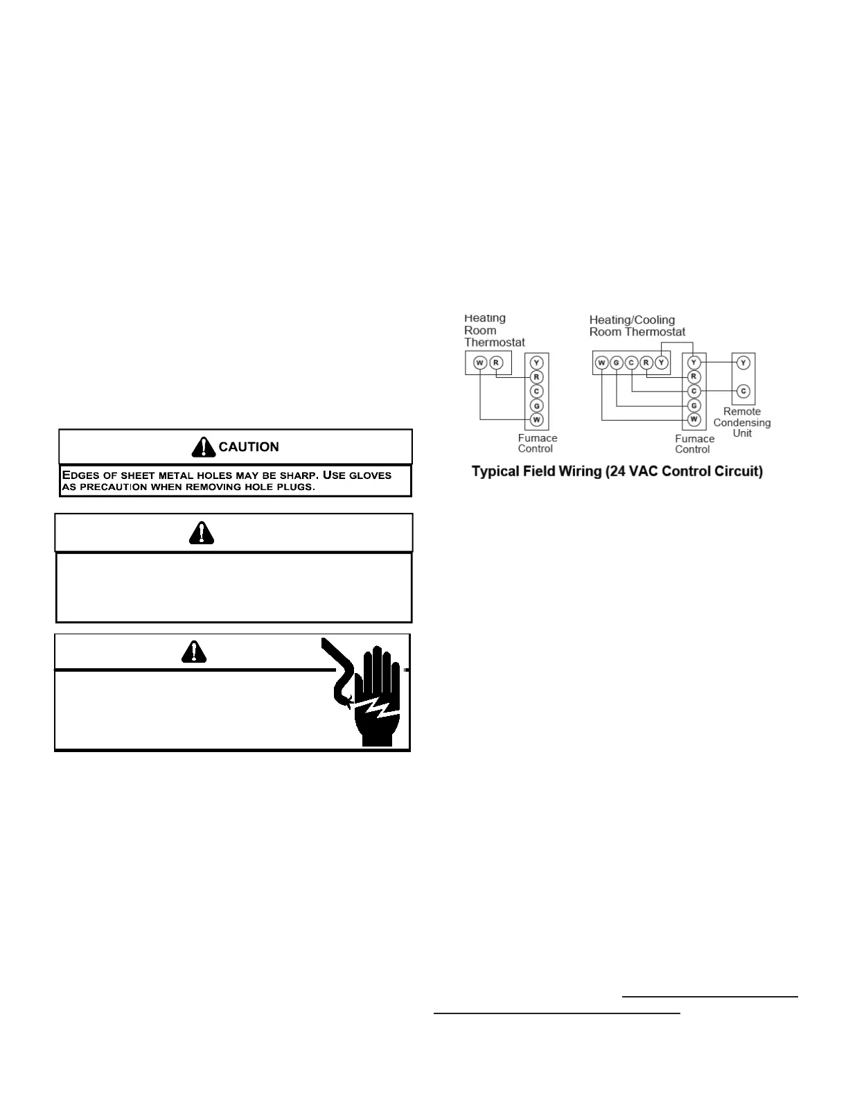
The single stage furnace will have a “W” terminal and will use
a single stage thermostat. The following drawing illustrates
the typical eld wiring for a heat only single stage system and
a single stage heating/single stage cooling system. Refer to
the following gures for proper connections to the integrated
control module.
CIRCULATING AIR AND FILTERS
Duct systems and register sizes must be properly designed
for the C.F.M. and external static pressure rating of the
furnace. Ductwork should be designed in accordance with
the recommended methods of “Air Conditioning Contractors
of America” manual D.
A duct system should be installed in accordance with
Standards of the National Board of Fire Underwriters for
the Installation of Air Conditioning, Warm Air Heating and
Ventilating Systems, Pamphlets No. 90A and 90B.
A return air lter is not supplied with the furnace. The installer
must supply a means of ltering all of the return air. Filter(s)
shall comply with UL900 or CAN/ULC-S111 Standards.
Upow furnaces with air delivery of less than 1800 CFM:
Use one side return or one bottom return ductwork connection.
Upow furnaces with air delivery of 1800 CFM or higher:
Use two side returns or one side return and one bottom return
connection.
Guide dimples locate the side and bottom return cutout
locations. Use a straight edge to scribe lines connecting the
dimples. Cut out the opening on these lines. An undersized
opening will cause reduced airflow. For bottom return
connection, remove the bottom of the cabinet before setting
the furnace on the raised platform or return air duct.
A closed return duct system must be used, with the return
duct connected to the furnace. NOTE: Ductwork must never
be attached to the back of the furnace. Supply and return
connections to the furnace may be made with exible joints
to reduce noise transmission, if desired. If a central return is
 Loading...