SYSTEM OPERATION
23
WARNING
I
E INRMAIN IN ESE INSRCINS IS N LLWED EXACL A
IRE R EXPLSIN MA RESL CASING PRPER DAMAGE PERSNAL
INJR R LSS LIE
–
D
O NOT STORE OR USE GASOLINE OR OTHER FLAMMABLE VAPORS AND
LIQUIDS IN THE VICINITY OF THIS OR ANY OTHER APPLIANCE.
–
WA
D
I
SMELL
GAS
•
D
O NOT TRY TO LIGHT ANY APPLIANCE.
•
D
O NOT TOUCH ANY ELECTRICAL SWITCH; DO NOT USE ANY
PHONE IN YOUR BUILDING.
•
I
MMEDIATELY CALL YOUR GAS SUPPLIER FROM A NEIGHBOR’S
PHONE.
F
OLLOW THE GAS SUPPLIER’S INSTRUCTIONS.
•
I
F YOU CANNOT REACH YOUR GAS SUPPLIER, CALL THE FIRE
DEPARTMENT.
–
I
NSTALLATION AND SERVICE MUST BE PERFORMED BY A QUALIFIED INSTALLER,
SERVICE AGENCY OR THE GAS SUPPLIER.
10
730 1,700 3,200 5,300 8,300 3,200 7,500
20 500 1,100 220
3,700 5,800 2,200 4,200
30 400 920 2,000 2,900 4,700 1,800 4,000
40
370 850 1,700 2,700 4,100
1,600 3,700
50 330 770
1,500 2,400 3,700 1,500
3,400
60
300 700 1,300 2,200 3,300 1,300 3,100
80 260 610 1,200
1,900 2,900
1,200 2,600
100 220 540 1,000 1,700 2,600 1,000 2,300
125
200 490 900 1,400 2,300 900 2,100
150 190 430 830 1,300 2,100 830 1,900
175 170
400 780 1,200
1,900 770 1,700
200 160
380 730 1,100 1,800 720 1,500
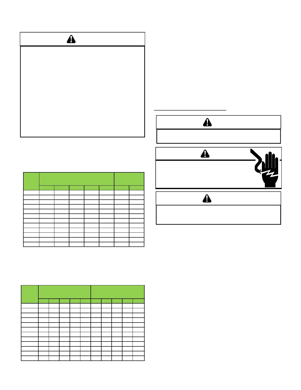
Maximum Propane Capacities listed are based on 2 psi g pr essure dr op at 10 psig setting .
Capaci ties i n 1,000 BTU/hour.
To convert to capacities at 15 psig settings - multiply by 1.130
To convert to capacities at 5 psig settings - multiply by 0.879
10 39 92 199 329 501 275 567 1,071
2,205 3,307
20 26 62 131 216 346 189 393 732 1,496 2,299
30 21 50 107 181 277 152 315 590 1,212 1,858
40 19 41 90 145 233 129 267 504 1,039 1,559
50 18 37 79 131 198 114
237 448 913 1,417
60 16 35 72 1,211 187 103 217 409 834 1,275
80 13 29 62 104 155 89 185 346 724
1,066
100 11 26 55 90 138 78 162 307 630 976
125 10 24 48 81 122
69 146 275 567 866
150 9 21 43 72 109 63 132 252 511 787
200 8 19 39
66
100
54 112 209 439 665
250 8
17 36 60 93 48 100 185 390 590
*Data in accordance with NFPA pamphlet No. 54
Maxi mum Propane Capaciti es listed ar e based on 1/2" W.C. pr essure dr op at 11" W.C. setti ng .
Capaci ties in 1,000 BTU/hour .
When installing a propane storage tank, the contractor
must consider proper tank sizing, safety, eciency, ground
characteristics and aesthetics. For a residential customer,
the size may range from 100-1,000 gallons, depending on
household use. Typically, a 500 gallon tank is ample for an
average four-bedroom home. However, it is best to consult
your local propane supplier to ensure the proper sizing for
propane storage requirements. Determining the correct tank
size for each household is a function of demand, economy,
eciency and convenience. It is a process that requires
cooperation between the propane supplier and customer.
WARNING
AVID E RISK ELECRICAL SCK WIRING E NI MS E
PRPERL PLARIED AND GRNDED
WARNING
IG
VLAGE
D
ISCNNEC
ALL
PWER ERE SERVICING R
INSALLING IS NI
M
LIPLE PWER SRCES MA
E PRESEN
AILRE D S MA CASE PRPER
DAMAGE PERSNAL INJR R DEA
LAEL ALL WIRES PRIR DISCNNECIN WEN SERVICING CNRLS
W
IRING ERRRS CAN CSE IMPRPER AND DANGERS PERAIN
V
ERI PRPER PERAIN AER SERVICING
The wiring harness is an integral part of this furnace. Field
alteration to comply with electrical codes should not be
required. Wires are color coded for identication purposes.
Refer to the wiring diagram for wire routings. If any of the
original wire as supplied with the furnace must be replaced,
it must be replaced with wiring material having a temperature
rating of at least 105° C. Any replacement wiring must be
copper conductor.
115 VOLT LINE VOLTAGE CONNECTION OF
ACCESSORIES (HUMIDIFIER AND ELECTRONIC AIR
CLEANER - 96% MODELS ONLY)
The furnace integrated control module is equipped with line
voltage accessory terminals for controlling power to an optional
eld-supplied humidier and/or electronic air cleaner.
The accessory load specications are as follows:
Turn OFF power to the furnace before installing any accessories.
Follow the humidier or air cleaner manufacturers’ instructions for
locating, mounting, grounding, and controlling these accessories.
Accessory wiring connections are to be made through the 1/4”
quick connect terminals provided on the furnace integrated control
module. The humidier and electronic air cleaner hot terminals
 Loading...