PRODUCT DESIGN
22
8. The furnace shall be connected to the building piping by
one of the following.
a. Rigid metallic pipe and fittings.
b. Semirigid metallic tubing and metallic fittings. Alu-
minum alloy tubing shall not be used in exterior
locations.
c. Listed gas appliance connectors used in accor-
dance with the terms of their listing that are com-
pletely in the same room as the equipment.
d. In "b" and "c" above, the connector or tubing shall
be installed so as to be protected against physi-
cal and thermal damage. Aluminum-alloy tubing
and connectors shall be coated to protect against
external corrosion where they are in contact with
masonry, plaster, or insulation or are subject to
repeated wettings by such liquids as water (ex-
cept rain water), detergents, or sewage.
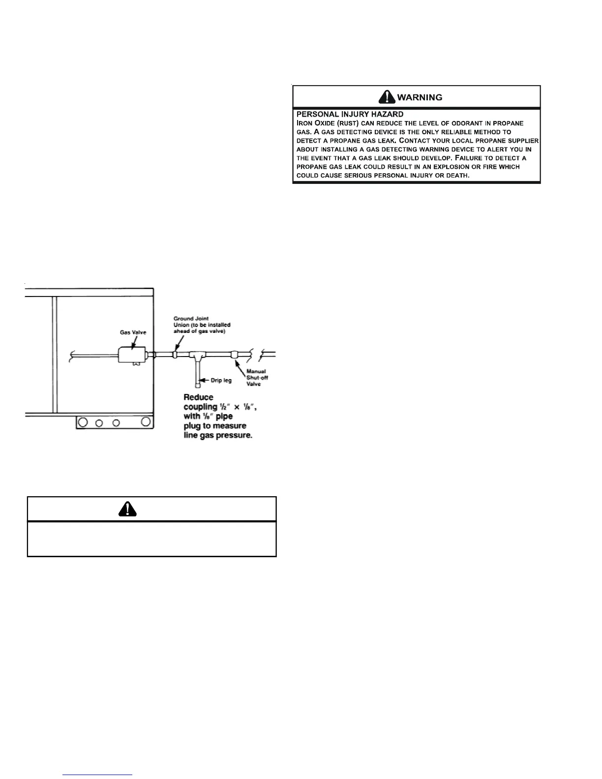
Figure 1
CHECKING THE GAS PIPING
CAUTION
T
O AVOID THE POSSIBILITY OF PROPERTY DAMAGE, PERSONAL INJURY OR
FIRE, THE FOLLOWING INSTRUCTIONS MUST BE PERFORMED REGARDING
GAS CONNECTIONS AND PRESSURE TESTING.
The unit and its gas connections must be leak tested before
placing in operation. Because of the danger of explosion or
fire, never use a match or open flame to test for leaks. Never
exceed specified pressure for testing. Higher pressure may
damage the gas valve and cause overfiring which may result
in heat exchanger failure.
This unit and its individual shutoff valve must be disconnected
from the gas supply piping system during any pressure test-
ing of that system at test pressures in excess of 1/2 psig
(3.48 kPa).
This unit must be isolated from the gas supply system by
closing its individual manual shutoff valve during any pres-
sure testing of the gas supply piping system at test pres-
sures equal to or less than 1/2 psig (3.48 kPa).
TANKS AND PIPING - PROPANE UNITS
All propane gas equipment must conform to the safety stan-
dards of the National Board of Fire Underwriters (See NBFU
Manual 58) or Natural Standards of Canada B149.2, Installa-
tion Code for Propane Gas Burning Appliances and Equip-
ment.
For satisfactory operation, propane gas pressure must be 10
inch W.C. at the furnace manifold with all gas appliances in
operation. Maintaining proper gas pressure depends on three
main factors.
1. Vaporization rate, which depends on (a) temperature of
the liquid, and (b) "wetted surface" area of the container
or containers.
2. Proper pressure regulation. (Two-stage regulation is rec-
ommended from the standpoint of both cost and efficiency.)
3. Pressure drop in lines between regulators, and between
second stage regulator and the appliance. Pipe size re-
quired will depend on length of pipe run and total load of
all appliances.
Complete information regarding tank sizing for vaporization,
recommended regulator settings, and pipe sizing is available
from most regulator manufacturers and propane gas suppli-
ers.
Propane is an excellent solvent, and special pipe dope must
be used when assembling piping for this gas as it will quickly
dissolve white lead or most standard commercial compounds.
Shellac base compounds resistant to the actions of liquefied
petroleum gases such as Gasolac, Stalactic, Clyde's or John
Crane are satisfactory.
Refer to Figure 2 for typical propane gas installations.
 Loading...