SERVICING
37
5. If line voltage available at primary voltage side of trans-
former and wiring and splices good, transformer is inop-
erative. Replace.
S-6 CHECKING TIME DELAY RELAY
Time delay relays are used in Amana
®
brand Package Units
to improve efficiency by delaying the blower off time. This
feature is incorporated into the electronic controls. See S-
23 to check control board.
S-7 CHECKING CONTACTOR AND/OR RELAYS
The compressor contactor and other relay holding coils are
wired into the low or line voltage circuits. When the control
circuit is energized the coil pulls in the normally open con-
tacts or opens the normally closed contacts. When the coil
is de-energized, springs return the contacts to their normal
position.
WARNING
HIGH
VOLTAGE
D
ISCONNECT ALL POWER BEFORE SERVICING OR
INSTALLING THIS UNIT.
M
ULTIPLE POWER SOURCES MAY
BE PRESENT.
FAILURE TO DO SO MAY CAUSE PROPERTY
DAMAGE, PERSONAL INJURY OR DEATH.
1. Remove the leads from the holding coil.
2. Using an ohmmeter, test across the coil terminals.
If the coil does not test continuous, replace the relay or
contactor.
S-8 CHECKING CONTACTOR CONTACTS
WARNING
D
ISCONNECT ELECTRICAL POWER SUPPLY.
1. Disconnect the wire leads from the terminal (T) side of
the contactor.
2. With power ON, energize the contactor.
WARNING
L
INE VOLTAGE NOW PRESENT.
3. Using a voltmeter, test across terminals.
A. L2 - T1 - No voltage indicates CC1 contacts open.
If a no voltage reading is obtained - replace the contactor.
S-9 CHECKING FAN RELAY CONTACTS
The fan relays are incorporated into the control board. See
sections S-23 for checking control board.
NOTE: Some variation over time has occurred in the fan re-
lays used. Refer to the unit wiring diagram for terminal iden-
tification.
S-15 CHECKING CAPACITOR
CAPACITOR, RUN
A run capacitor is wired across the auxiliary and main wind-
ings of a single phase permanent split capacitor motor. The
capacitors primary function is to reduce the line current while
greatly improving the torque characteristics of a motor. This
is accomplished by using the 90° phase relationship between
the capacitor current and voltage in conjunction with the motor
windings so that the motor will give two phase operation when
connected to a single phase circuit. The capacitor also re-
duces the line current to the motor by improving the power
factor.
CAPACITOR, START
SCROLL COMPRESSOR MODELS
Hard start components are not required on Scroll compres-
sor equipped units due to a non-replaceable check valve lo-
cated in the discharge line of the compressor. However hard
start kits are available and may improve low voltage starting
characteristics.
This check valve closes off high side pressure to the com-
pressor after shut down allowing equalization through the scroll
flanks. Equalization requires only about one or two seconds
during which time the compressor may turn backwards.
To prevent the compressor from starting and running back-
wards a Time Delay Relay (Cycle Protector) has been added
to the low voltage circuit.
NOTE: K3 series scroll compressors have an anti-rotation
device and equalizing mechanism incorporated into the com-
pressor and will equalize in 0.2 to 0.3 seconds. These com-
pressors will operate correctly without a Time Delay Relay.
MODELS EQUIPPED WITH A HARD START DEVICE
A start capacitor is wired in parallel with the run capacitor to
increase the starting torque. The start capacitor is of the
electrolytic type, rather than metallized polypropylene as used
in the run capacitor.
A switching device must be wired in series with the capacitor
to remove it from the electrical circuit after the compressor
starts to run. Not removing the start capacitor will overheat
the capacitor and burn out the compressor windings.
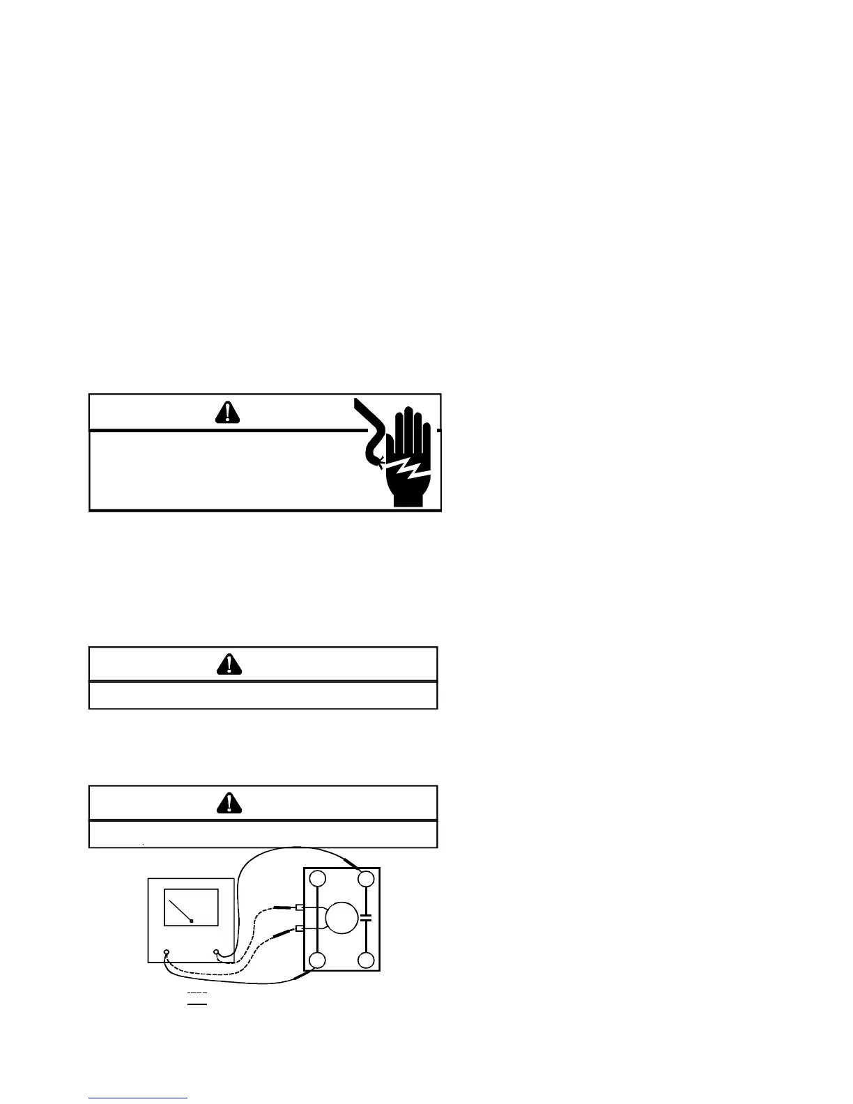
VOLT/OHM
METER
T1
T2
L1L2
CC
Ohmmeter for testing holding coil
Voltmeter for testing contacts
TESTING COMPRESSOR CONTACTOR
 Loading...