SERVICING
56
CAUTION
D
O NOT ALLOW THE SLUDGE OR OIL TO CONTACT THE SKIN.
S
EVERE
BURNS MAY RESULT.
NOTE: The Flushing Method using R-11 refrigerant is no
longer approved by Goodman Company, L.P.
Suction Line Drier Clean-Up Method
Use AMANA® brand part number R0157057 Suction Line
Drier Clean-Up Kit (41 cubic inches). This drier should be
installed as close to the compressor as possible, either in a
vertical or horizontal position. It may be necessary to use
new tubing and form as required.
In all applications, the drier inlet must be above the drier out-
let to provide proper oil return to the compressor.
NOTE: At least twelve (12) inches of the suction line imme-
diately out of the compressor stub must be discarded due to
burned residue and contaminates.
1. Remove compressor discharge line strainer, liquid line
strainer and/or dryer and capillary tubes from indoor and
outdoor coils.
2. On an expansion valve coil, remove the liquid line drier
and expansion valve.
3. Purge all remaining components with dry nitrogen or car-
bon dioxide until clean.
4. Install new components including liquid liner drier.
5. Install suction line drier.
6. Braze all joints, leak test, evacuate, and recharge sys-
tem.
7. Start up the unit and record the pressure drop across the
cleanup drier.
8. Continue to run the system for a minimum of twelve (12)
hours and recheck the pressure drop across the drier.
Pressure drop should not exceed 6 - 8 PSIG.
9. Continue to run the system for several days repeatedly
checking pressure drop across the suction line drier. If
the pressure drop never exceeds the 6 - 8 PSIG, the drier
must be adequate and is trapping the contaminants and
it is permissible to leave it in the system.
10. If the pressure drop becomes greater, then it must be
replaced and steps 5 through 9 repeated until it does not
exceed 6 - 8 PSIG.
NOTICE: Regardless, the cause for burnout must be deter-
mined and corrected before the new compressor is started.
S-200 CHECKING EXTERNAL STATIC PRES-
SURE
The minimum and maximum allowable duct static pressure
is found in the specification section.
Too great of an external static pressure will result in insuffi-
cient air that can cause icing of the coil, whereas too much
air can cause poor humidity control, and condensate to be
pulled off the evaporator coil causing condensate leakage.
Too much air can cause motor overloading and in many cases
this constitutes a poorly designed system. To determine
proper air movement, proceed as follows:
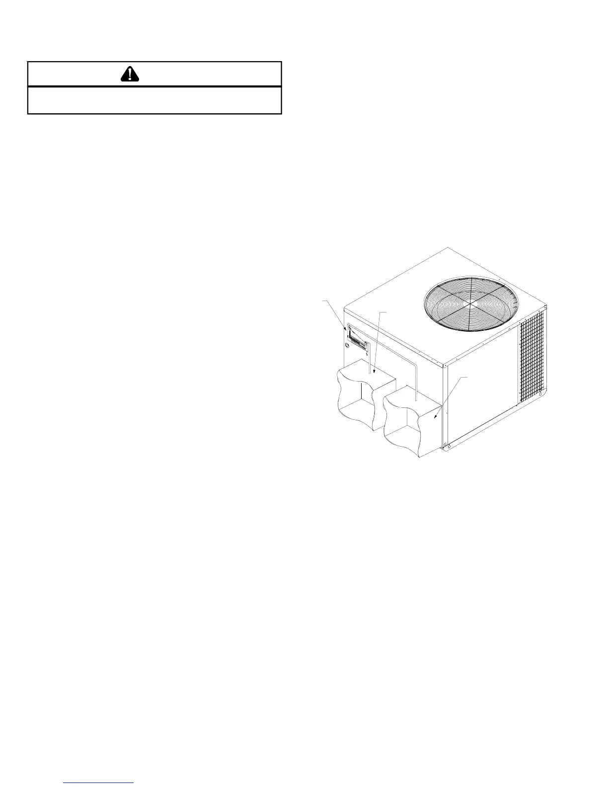
1. Using a draft gauge (inclined manometer) measure the
static pressure of the return duct at the inlet of the unit,
(Negative Pressure).
RETURN
SUPPLY
INCLINED
MANOMETER
TOTAL EXTERNAL STATIC
2. Measure the static pressure of the supply duct, (Positive
Pressure).
3. Add the two readings together.
NOTE: Both readings may be taken simultaneously and read
directly on the manometer if so desired.
4. Consult proper table for quantity of air.
If the external static pressure exceeds the minimum or maxi-
mum allowable statics, check for closed dampers, dirty fil-
ters, undersized or poorly laid out ductwork.
S-300 TESTING PRIMARY LIMIT CONTROL
Amana
®
brand Package Gas Units use a snap-disk type pri-
mary limit device. Sometimes referred to as "stat on a stick".
The limit setting is fixed and must not be readjusted in the
field.
 Loading...