SERVICING
47
NOTE: The positive temperature coefficient crankcase heater
is a 40 watt 265 voltage heater. The cool resistance of the
heater will be approximately 1800 ohms. The resistance will
become greater as the temperature of the compressor shell
increases.
S-21 CHECKING REVERSING VALVE AND SO-
LENOID
Occasionally the reversing valve may stick in the heating or
cooling position or in the mid-position.
When stuck in the mid-position, part of the discharge gas
from the compressor is directed back to the suction side,
resulting in excessively high suction pressure. An increase
in the suction line temperature through the reversing valve
can also be measured. Check operation of the valve by start-
ing the system and switching the operation from COOLING
to HEATING cycle.
If the valve fails to change its position, test the voltage (24V)
at the valve coil terminals, while the system is on the COOL-
ING cycle.
If no voltage is registered at the coil terminals, check the
operation of the reversing relay and the continuity of the con-
necting wires.
If voltage is registered at the coil, tap the valve body lightly
while switching the system from HEATING to COOLING, etc.
If this fails to cause the valve to switch positions, remove the
coil connector cap and test the continuity of the reversing
valve solenoid coil. If the coil does not test continuous -
replace it.
If the valve is inoperative - replace it.
S-22 REVERSING VALVE REPLACEMENT
Remove the refrigerant charge from the system.
When brazing a reversing valve into the system, it is of ex-
treme importance that the temperature of the valve does not
exceed 250°F. at any time.
Wrap the reversing valve with a large rag saturated with wa-
ter. "Re-wet" the rag and thoroughly cool the valve after each
brazing operation of the four joints involved. The wet rag
around the reversing valve will eliminate conduction of heat to
the valve body when brazing the line connection.
The use of a wet rag sometimes can be a nuisance. There
are commercial grades of heat absorbing paste that may be
substituted.
After the valve has been installed, leak test, evacuate and
recharge.
S-24 TESTING DEFROST BOARD
The Defrost Control Board is an electronic device which is
not field repairable. If a malfunction should occur the com-
plete board must be replaced. The board has anti-short cycle
protection, high and low pressure switch interrupts incorpo-
rated into the control.
Normal sequence of operation, Cooling Mode.
1. If the compressor has been off for at least 3 minutes when
a call for cool is received, the compressor is immediately
energized. The indoor blower is energized at the cooling
speed after a 7 second delay.
2. If the compressor has not been off for at least 3 minutes
when a call for cooling is received, the control waits at
least 3 minutes before energizing the compressor. The
LED will flash 6 times when the compressor is delayed
on the anti-short cycle timer.
4. If power to the control is interrupted, the compressor will
be energized after a 3 minute delay after power is re-
applied to the control. The control will flash 6 times to
indicate the compressor is delayed on the anti-short cycle
timer.
5. The control de-energizes the indoor blower 60 seconds
after the call for cooling is removed.
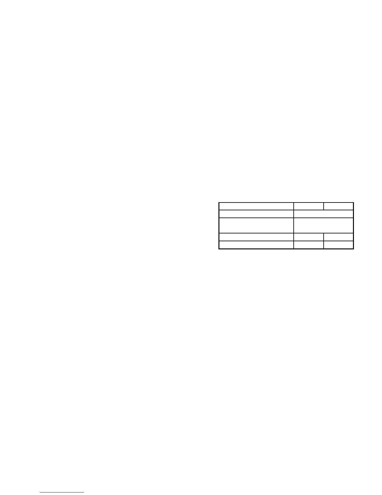
This control has a self diagnostic feature. Before performing
any test observe the LED indicators and compare to the chart
below for board status.
DIAGNOSTICS
LED 1 LED 2
NORMAL OPERATION
SHORT CYCLE
LTERNATING
FLASHING
LOCKOUT
ON OFF
BOARD FAILURE
ON ON
BOTH FLASHING
Normal sequence of operation, Heating Mode.
1. If the compressor has been off for at least 3 minutes when
a call for heat is received, the compressor is immediately
energized. The indoor blower is energized at the cooling
speed after a 7 second delay.
2. If the compressor has not been off for at least 3 minutes
when a call for heating is received, the control waits at
least 3 minutes before energizing the compressor. The
LED will flash 6 times when the compressor is delayed
on the anti-short cycle timer.
4. If power to the control is interrupted, the compressor will
be energized after a 3 minute delay after power is re-
applied to the control. The control will flash 6 times to
indicate the compressor is delayed on the anti-short cycle
timer.
The following has been simplified in order to illustrate the
Electronic functions:
5. When the defrost thermostat (30/60 control) closes (coil
temperature at approximately 30°F.), the solid state board
becomes programmed.
 Loading...