SERVICING
48
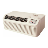
DEFROST CONTROL BOARD
NOTE: If the board is powered up with the jumper connected
to the test pins, the board will ignore test and default to 90
minute time. If the jumper is left on the test connection for
more than ten minutes, the board will ignore test jumper and
default to 90 minute time. If jumper is missing, the board will
default to 90 minute time.
6. Whenever the (CC) compressor contactor is energized,
the solid state timer counts the compressor run time.
Total accumulated minutes (run time) is retained as long
as the Defrost (30/60) control stays closed. With the
jumper connected to the 90 minute pins, the compressor
run time is 90 minutes (factory wired). The board has
jumper pin for 60 and 30 minute times as well.- Timer
count time may be accelerated for testing only, by plac-
ing jumper on test pins. (Example: 90 minutes = ap-
proximately 21 seconds). Remove the jumper when the
board goes into defrost mode. If the jumper is not re-
moved, the timer will remain accelerated through the de-
frost period.
7. At end of the programmed time, common circuit (C) is
made to the (OUT) terminal. The reversing solenoid be-
comes energized and will stay energized until defrost (30/
60) control opens by coil temperature, or after 10 min-
utes of run time. Maximum defrost time limited to 10 min-
utes compressor run time. During the defrost time, the
board will apply power to the "W" terminal to bring on
supplemental electric heat (if installed).
8. The control de-energizes the indoor blower 60 seconds
after the call for heating is removed.
To check the defrost timer board for proper sequencing, pro-
ceed as follows: With power ON; unit not running.
O
OUT
DF
PS1
PS2
P
S
1
COMMON
Y1 OUT
FAN
E
C
R
W
O
Y
2
1
A
B
A
R
G
G
YL-5
SEE
DETAIL 1
TEST
60
DETAIL 1
HEATCRAFT
ADJUSTABLE DEFROST INTERVAL
(FACTORY SETTING AS SHOWN)
30
90
DEFROST
CONTROL
COOLING
SWITCH
RELAY
FUSE
OR
28
GY
55
GY-8
RD-24
DIAGNOSTICS
LED
DEFROST
THERMOSTAT
REVERSING
SOLENOID
O. D.
FAN
MOTOR
+ 24 V
Heatcraft Defrost Board
1. Jumper defrost (30/60 control by placing a jumper wire
across "DF" terminals.) terminal at defrost timer board.
2. Connect jumper across test pins on defrost control board.
3. Set thermostat to call for heating. System should go into
defrost within 21 seconds.
4. Immediately remove jumper from test pins.
5. Using VOM check for voltage across OUT Terminals (BK-
19 & BK-20). meter should read 24 volts.
6. Using VOM check for voltage across Fan terminals on
the board (VT-62 & VT-16). You should read line voltage
(208-230 VAC) indicating the relay is open in the defrost
mode.
7. Using VOM check for voltage across "W & C" terminals
on the board. You should read 24 volts.
8. If not as above, replace control board.
9. Set thermostat to off position and disconnect power be-
fore removing any jumpers or wires.
NOTE: Remove jumper across defrost thermostat and replace
jumper to 30, 60, or 90 minute position before returning sys-
tem to service.
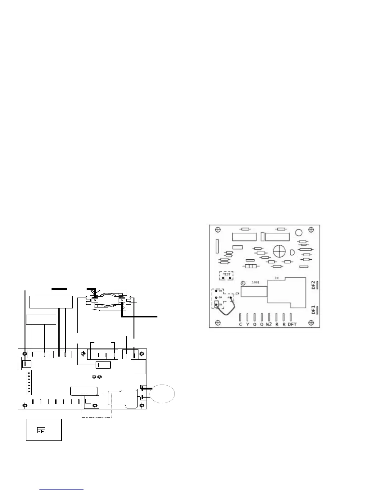
Ranco Defrost Board
Ranco Defrost Board
1. Jumper defrost (30/60) control by placing a jumper wire
across "DFS" terminals at defrost timer board.
2. Connect jumper across test pins on defrost control board.
3. Set thermostat to call for heating. System should go into
defrost within 21 seconds.
4. Immediately remove jumper from test pins.
5. Using VOM check for voltage across RV Terminals. Meter
should read 24 volts.
6. Using VOM check for voltage between the "DF1" and
"DF2" terminals on the board. You should read line volt-
age (208-230 VAC) indicating the relay is open in the
defrost mode.
 Loading...