PRODUCT DESIGN
21
The best protection for the wiring is the smallest fuse or breaker
which will hold the equipment on line during normal operation
without nuisance trips. Such a device will provide maximum
circuit protection.
DO NOT EXCEED THE MAXIMUM OVERCURRENT DEVICE
SIZE SHOWN ON THE UNIT DATA PLATE.
All line voltage connections must be made through weather
proof fittings. All exterior power supply and ground wiring
must be in approved weather proof conduit. Low voltage wir-
ing from the unit control panel to the thermostat requires coded
cable. Unit knock out sizes are shown in the specification
tables.
The unit transformer is connected for 230V operation. If the
unit is to operate on 208V, reconnect the transformer pri-
mary lead and the induced draft blower leads as shown on
the unit wiring diagram.
WARNING
T
O AVOID THE RISK OF FIRE, PROPERTY DAMAGE OR PERSONAL INJURY,
USE ONLY COPPER CONDUCTORS.
If it is necessary for the installer to supply additional line
voltage wiring to the inside of the package unit, the wiring
must comply with all local codes. This wiring must have a
minimum temperature rating of 105°C. and must be routed
away from the burner compartment. All line voltage splices
must be made inside the furnace junction box.
GAS SUPPLY AND PIPING
Package Gas Units
CAUTION
T
HIS
P
ACKAGE
G
AS
U
NIT IS FACTORY SET TO OPERATE ON NATURAL
GAS AT THE ALTITUDES SHOWN ON THE RAITNG PLATE.
I
F OPERATION ON
PROPANE IS REQUIRED, OBTAIN AND INSTALL THE PROPER CONVERSION
KIT(S) BEFORE OPERATING THIS FURNACE.
F
AILURE TO DO SO MAY RESULT
IN UNSATISFACTORY OPERATION AND/OR EQUIPMENT DAMAGE.
The rating plate is stamped with the model number, type of
gas, and gas input rating. Make sure the furnace is equipped
to operate on the type of gas available.
INLET GAS PRESSURE
NATURAL MIN. 5.0", MAX. 10.0"
PROPANE MIN. 11.0", MAX. 14.0"
Inlet Gas Pressure Must Not Exceed the Maximum Value
Shown in the table Above.
The minimum supply pressure must not be varied downward
because this could lead to unreliable ignition. In addition,
gas input to the burners must not exceed the rated input
shown on the rating plate. Overfiring of the furnace could
result in premature heat exchanger failure.
GAS PIPING
CAUTION
T
O AVOID POSSIBLE UNSATISFACTORY OPERATION OR EQUIPMENT DAMAGE
DUE TO UNDERFIRING OF EQUIPMENT, DO NOT UNDERSIZE THE NATURAL
GAS/PROPANE PIPING FROM THE METER/TANK TO THE FURNACE.
WHEN
SIZING A TRUNK LINE PER THE TABLES, INCLUDE ALL APPLIANCES ON THAT
LINE THAT COULD BE OPERATED SIMULTANEOUSLY.
The gas pipe supplying the furnace must be properly sized
based on the cubic feet per hour of gas flow required, specific
gravity of the gas and length of the run. The gas line installa-
tion must comply with local codes, or in the absence of local
codes, with the latest edition of the National Fuel Gas Code
ANSI Z223.1.
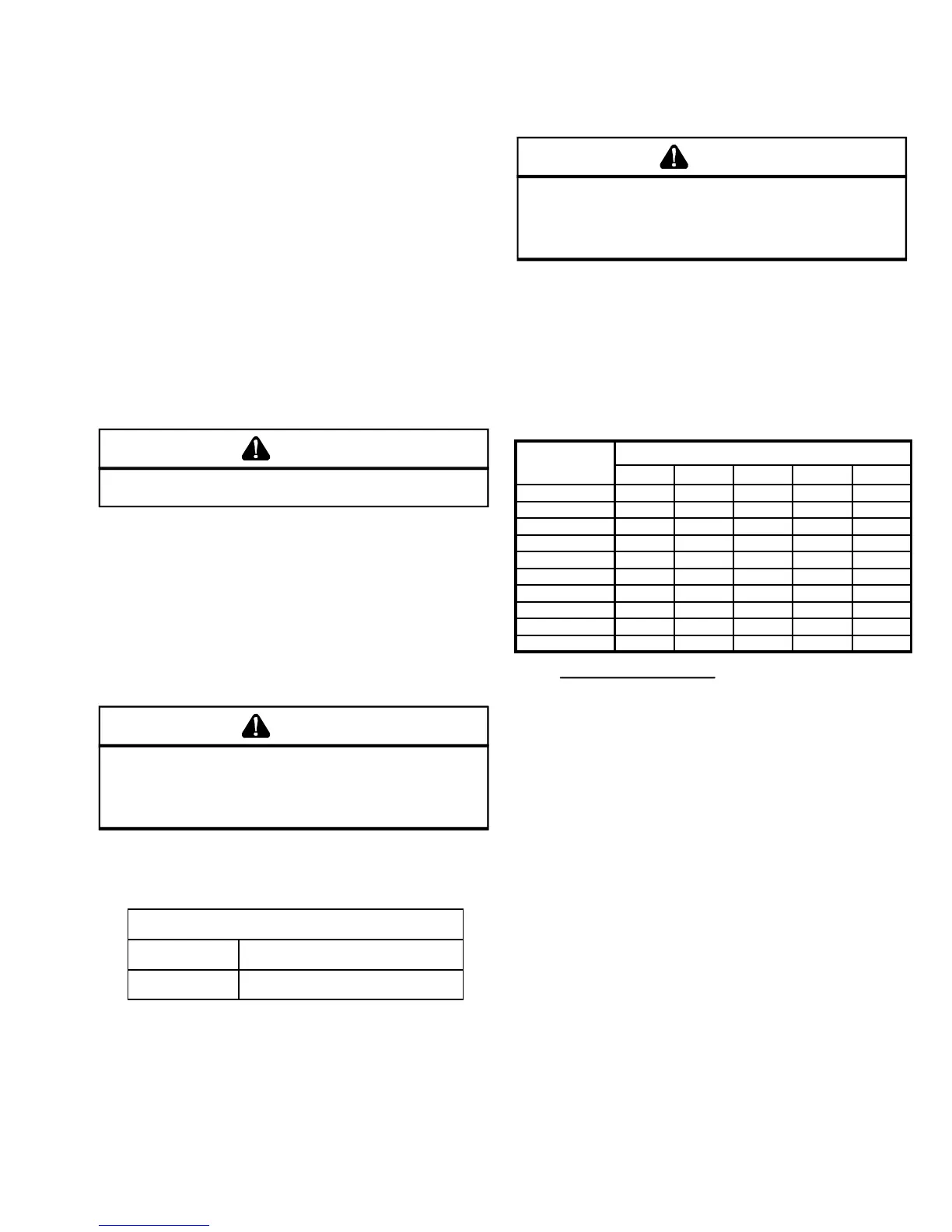
NATURAL GAS CAPACITY OF PIPE IN CUBIC FEET OF
GAS PER HOUR (CFH)
LENGTH OF
PIPE IN FEET
NOMINAL BLACK PIPE SIZE
1/2" 3/4" 1" 1 1/4" 1 1/2"
10 132 278 520 1050 1600
20 92 190 350 730 1100
30 73 152 285 590 980
40 63 130 245 500 760
50 56 115 215 440 670
60 50 105 195 400 610
70 46 96 180 370 560
80 43 90 170 350 530
90 40 84 160 320 490
100 38 79 150 305 460
BTUH FURNACE INPUT
CALORIFIC VALUE OF GAS
CFH =
CONNECTING THE GAS PIPING - NATURAL GAS
Refer to the figure 1 for the general layout of the furnace. The
following rules apply:
1. Use black iron or steel pipe and fittings for the building
piping.
2. Use pipe joint compound on male threads only. Pipe
joint compound must be resistant to the action of the fuel
used.
3. Use ground joint unions.
4. Install a drip leg to trap dirt and moisture before it can
enter the gas valve. The drip leg must be a minimum of
three inches long.
5. Use two pipe wrenches when making connection to the
gas valve to keep it from turning.
6. Install a manual shut off valve. This shut off valve should
be conveniently located within six (6) feet of the unit, and
between the meter and unit.
7. Tighten all joints securely.
 Loading...