SERVICING
51
Moisture chemically reacts with the refrigerant and oil to form
corrosive hydrofluoric and hydrochloric acids. These attack
motor windings and parts, causing breakdown.
The equipment required to thoroughly evacuate the system
is a high vacuum pump, capable of producing a vacuum equiva-
lent to 25 microns absolute and a thermocouple vacuum gauge
to give a true reading of the vacuum in the system
NOTE: Never use the system compressor as a vacuum pump
or run when under a high vacuum. Motor damage could oc-
cur.
WARNING
SCROLL COMPRESSORS: DO NOT FRONT SEAT THE SERVICE VALVE(S)
WITH THE COMPRESSOR OPERATING IN AN ATTEMPT TO SAVE REFRIGERANT.
W
ITH THE SUCTION LINE OF THE COMPRESSOR CLOSED OR SEVERALLY
RESTRICTED, THE SCROLL COMPRESSOR CAN AND WILL DRAW A DEEP
VACUUM VERY QUICKLY.
THIS VACUUM CAN CAUSE INTERNAL ARCING OF
THE FUSITE RESULTING IN A DAMAGED OR FAILED COMPRESSOR.
LOW SIDE
GAUGE
AND VALVE
HIGH SIDE
GAUGE
AND VALVE
TO
UNIT SERVICE
VALVE PORTS
VACUUM PUMP
VACUUM PUMP
ADAPTER
800 PSI
RATED
HOSES
CHARGING
CYLINDER
AND SCALE
{
R-22
MANIFOLD
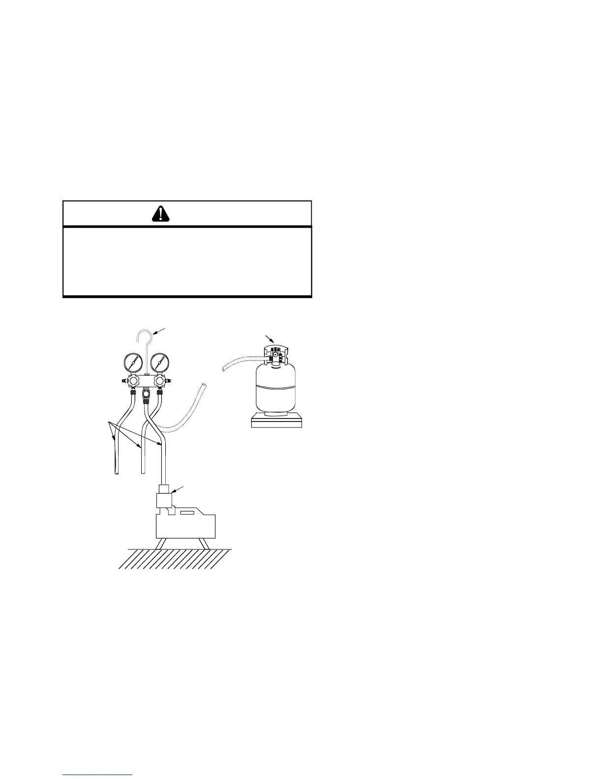
EVACUATION
1. Connect the vacuum pump, vacuum tight manifold set
with high vacuum hoses, thermocouple vacuum gauge
and charging cylinder as shown.
2. If the service dill valves are to be used for evacuation, it is
recommended that a core remover be used to lift the core
for greater efficiency.
high vacuum gauge manifold only. After the compound
gauge (low side) has dropped to approximately 29 inches
of vacuum, open the valve to the vacuum thermocouple
gauge. See that the vacuum pump will blank-off to a
maximum of 25 microns. A high vacuum pump can only
produce a good vacuum if its oil is non-contaminated.
4. If the vacuum pump is working properly, close the valve to
the vacuum thermocouple gauge and open the high and
low side valves to the high vacuum manifold set. With
the valve on the charging cylinder closed, open the mani-
fold valve to the cylinder.
5. Evacuate the system to at least 29 inches gauge before
opening valve to thermocouple vacuum gauge.
6. Continue to evacuate to a minimum of 250 microns. Close
valve to vacuum pump and watch rate of rise. If vacuum
does not rise above 1500 microns in three to five min-
utes, system can be considered properly evacuated.
7. If thermocouple vacuum gauge continues to rise and lev-
els off at about 5000 microns, moisture and non-condens-
ables are still present. If gauge continues to rise a leak
is present. Repair and re-evacuate.
8. Close valve to thermocouple vacuum gauge and vacuum
pump. Shut off pump and prepare to charge.
S-103 CHARGING
Charge the system with the exact amount of refrigerant.
Refer to the specification section or check the unit name-
plates for the correct refrigerant charge.
An inaccurately charged system will cause future problems.
1. When using an ambient compensated calibrated charg-
ing cylinder, allow liquid refrigerant only to enter the high
side.
2. After the system will take all it will take, close the valve
on the high side of the charging manifold.
3. Start the system and charge the balance of the refriger-
ant through the low side. DO NOT charge in a liquid
form.
4. With the system still running, close the valve on the charg-
ing cylinder. At this time, you may still have some liquid
refrigerant in the charging cylinder hose and will definitely
have liquid in the liquid hose. Reseat the liquid line core.
Slowly open the high side manifold valve and transfer the
liquid refrigerant from the liquid line hose and charging
cylinder hose into the suction service valve port. CARE-
FUL: Watch so that liquid refrigerant does not enter the
compressor.
5. With the system still running, reseat the suction valve
core, remove hose and reinstall both valve core caps.
6. Check system for leaks.
3. Start the vacuum pump and open the shut off valve to the
 Loading...