28
SYSTEM OPERATION
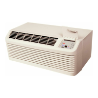
Figure 9 illustrates the pressure control in an off position.
CONNECTOR
COMMON
TERMINAL
NORMALLY OPEN
TERMINAL
NEGATIVE PRESSURE
Figure 9
With the furnace in the off position the induced draft blower
motor will not be running. Atmospheric pressure will there-
fore be on both sides of the diaphragm and the electrical
switch will be open between (C) common and (NO) normally
open terminals.
When the induced draft blower motor is in operation, the J-
tube hose will create a negative pressure on one side of the
diaphragm and atmospheric pressure will be on the other
side causing the diaphragm to move toward the negative pres-
sure.
This in turn will close the switch and make the (C) common
to the (NO) normally open terminals.
In the event of partially restricted or blocked flue the induced
draft blower will create less negative pressure and at approxi-
mately -0.32" +.06 W.C. negative pressure would open the
contacts (C) to (NO).
OPERATING INSTRUCTIONS
1. Close the manual gas valve external to the unit.
2. Turn off the electrical power supply to the unit.
3. Set the room thermostat to its lowest possible setting.
4. Remove the heat exchanger door on the side of the unit
by removing screws.
5. This unit is equipped with an ignition device which auto-
matically lights the pilot. DO NOT try to light burner by
any other method.
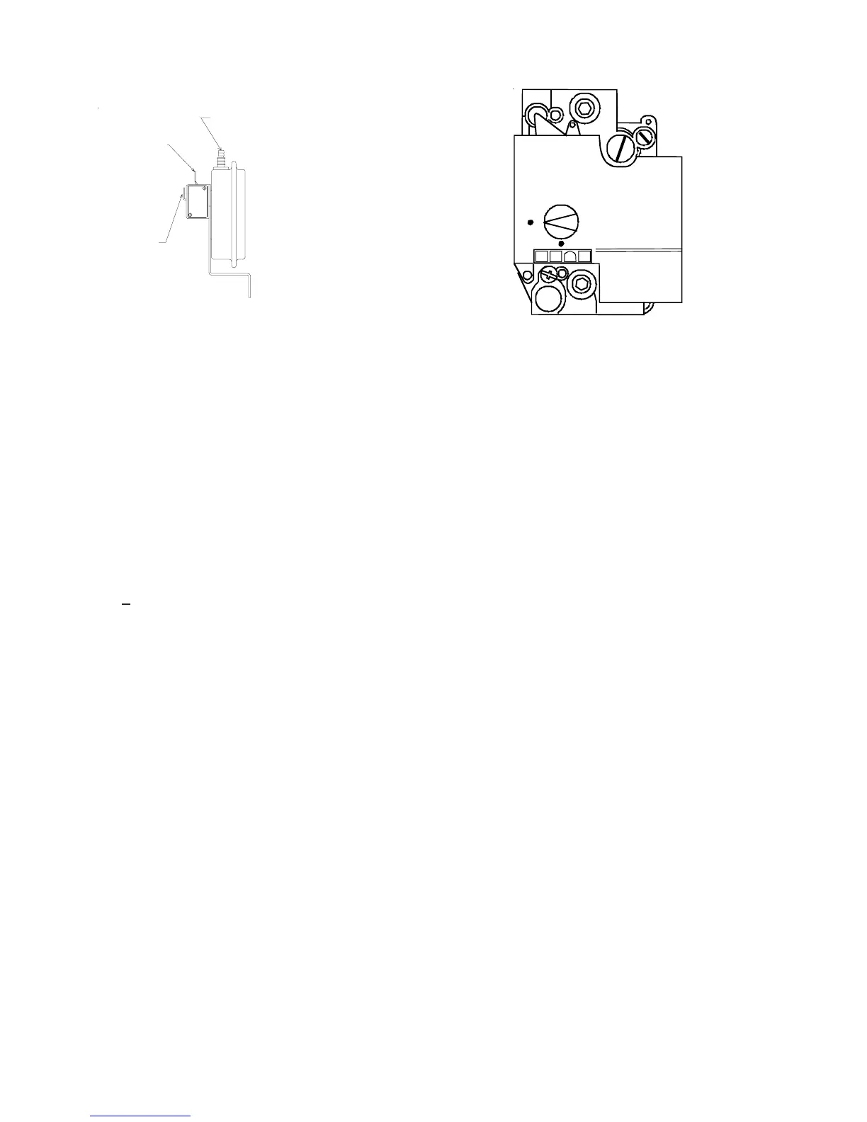
6. Turn the gas control valve knob to the OFF position. Do
not force. Some Gas valves may have a different off/on
style switch.
OFF
ON
Figure 10
7. Wait five minutes to clear out any gas.
8. Smell for gas, including near the ground. This is impor-
tant because some types of gas are heavier than air. If
you have waited five minutes and you do smell gas, im-
mediately follow the instructions on the Page 13 of this
manual. If having waited for five minutes and no gas is
smell is noted, turn the gas control valve knob to the ON
position.
9. Replace the heat exchanger door on the side of the unit.
10. Open the manual gas valve external to the unit.
11. Turn on the electrical power supply to the unit.
12. Set the thermostat to desired setting.
NOTE: There is approximate 20 second delay between ther-
mostat energizing and burner firing.
FAN OPERATION
Continuous Fan Mode
If the thermostat calls for continuous fan without a call for
heat or cool, the indoor blower will be energized at the heat
speed after a 7 second on delay. The fan remains energized
as long as there is not a call for heat or cool. Once the call
for continuous fan is de-energized, the indoor blower will go
through a 30 second off delay.
If a call for cool occurs during continuous fan operation, the
blower will switch to the cooling speed after the 7 second
cool on delay.
If a call for heat occurs during continuous fan operation, the
indoor blower will de-energize when the heat on blower delay
begins. The heat cycle will control the indoor blower opera-
tion until the heat blower off delay is over. The continuous
fan mode will function normally even while the control is in
heat lockout.
 Loading...