SERVICING
40
8
7
6
5
4
3
2
1
16
15
14
13
12
11
10
9
OUT -
ADJUST +/-
Y 1
COOL
DELAY
COMMON 2
W/W1
COMMON 1
OUT +
G (fan)
Y/Y2
EM HT/W2
24VAC (R)
HEAT
BK/Pwm (Speed)
O (Rev Valve)
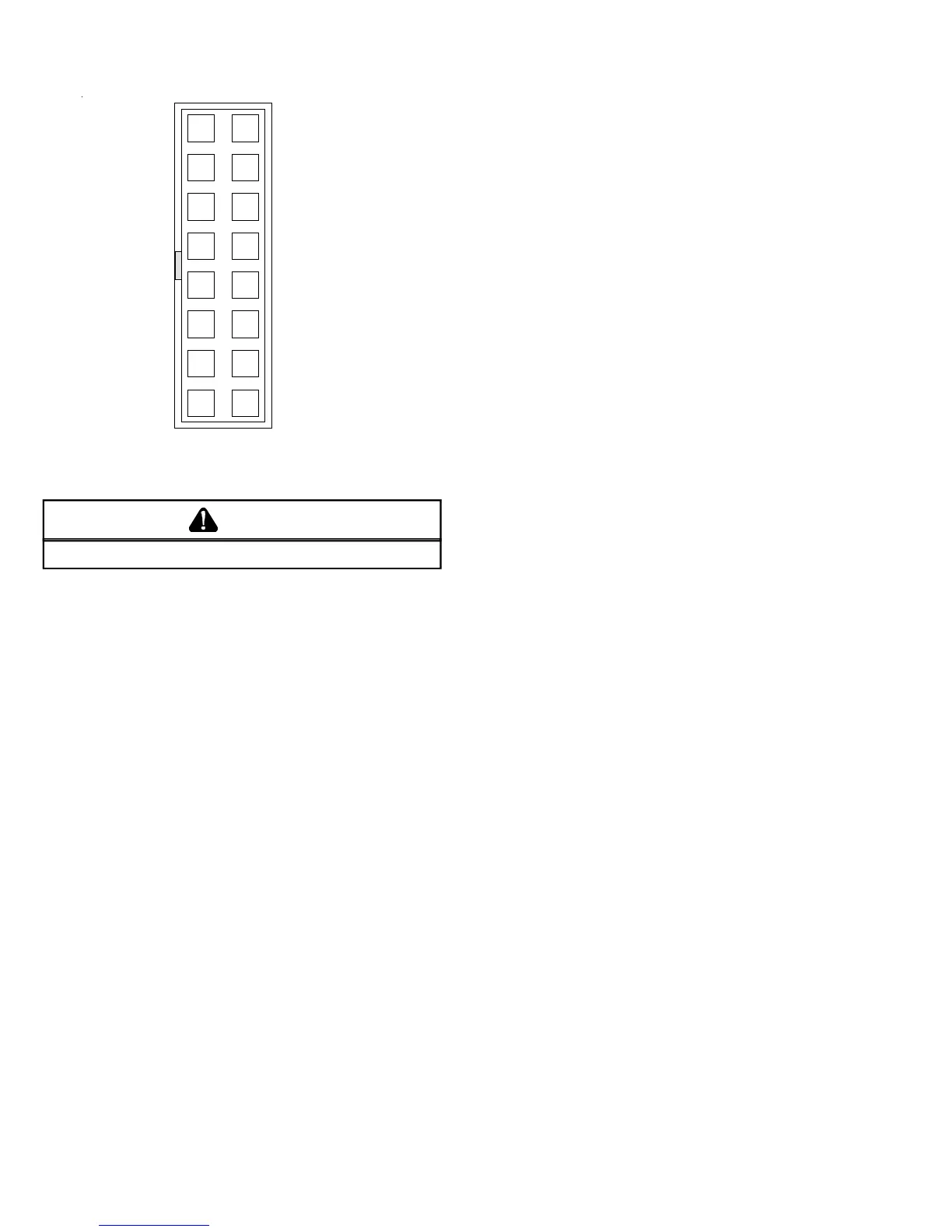
CONTROL CONNECTOR
"Motor Half“
CAUTION
H
IGH VOLTAGE ON CONTROL PINS WILL DESTROY MOTOR.
Replacing ICM Control Module
Use the following steps to replace the control module for the
GE
©
variable speed indoor blower motor.
1. You must have the correct replacement module. The con-
trols are factory programmed for specific operating modes.
Even though they look alike, different modules may have
completely different functionality. Using the wrong con-
trol module voids all product warranties and may produce
unexpected results.
2. Remove all power from the unit being serviced. Do not
work on the motor with power applied. Wait at least 5
minutes after disconnecting power from the equipment
before opening the motor.
3. It is usually not necessary to remove the motor from the
blower assembly. However it is recommended that the
whole blower assembly, with the motor, be removed.
Unplug the two cable connectors to the motor. There are
latches on each connector. Do not pull on the wires. The
plugs remove easily when properly released.
4. Observe the flat end of the motor control module casting
and located the two standard ¼" hex head bolts. Remove
these bolts from the motor while holding the control mod-
ule. Do not remove the two torx head screws.
5. The control module is now free of the motor but still at-
tacked by a plug and cable. Carefully rotate the control
so as to gain access to the plug on the end of the cable.
Squeeze the release latch and gently pull the plug out of
the control module. Do not pull on the wires. Grip the
plug only.
6. The control module is now completely detached from the
motor. Verify with a standard ohmmeter that the resis-
tance from each motor lead (in the motor plug just re-
moved) to the motor shell is greater than 100k ohms.
(Measure resistance to unpainted motor end plate). If any
motor lead fails this test do not proceed to install the
control module. The motor is defective and must be re-
placed. Installing the new control module will cause it to
fail also.
7. Verify that the replacement control module is correct for
your application. If so, orient the new module next to the
motor and carefully insert the plug removed in step 5. Be
sure the plug latches. It will click when properly inserted.
8. Install the new control module back on the motor being
careful to engage the locating pin into the appropriate
mating motor hole. Replace the two 1/4" hex head bolts.
Tighten the bolts snugly. It is not necessary to overtighten.
Note: Before replacing the blower/motor assembly, it is im-
portant to look at the installation to see if some application
fault has caused the motor to fail.
Is there any evidence of water damage to the failed control?
(Corrosion on the inside or outside of the casting.) If yes, do
moisture check.
9. Re-install the blower/motor assembly into the package
unit.
10. Plug the 16-pin control plug into the motor. The plug is
keyed. Make sure the connector is properly seated and
latched.
11. Plug the 5 pin power connector into the motor even though
the plug is keyed, observe the proper orientation. Do not
force the connector. It plugs in very easily when properly
oriented. Reversing this plug will cause immediate
failure of the control module.
12. Final installation check. Make sure the motor is installed
as follows:
A. As far into the blower housing as possible
B. Belly bands not covering vent holes or on the con-
trol module
C. Motor connectors should oriented as to prevent
the accumulation of moisture in the control.
D. Use wire ties to create a drip loop in the motor
cables.
13. The installation is now complete. Reapply power to the
package unit and verify that the new motor control mod-
ule is working properly.
 Loading...