SERVICING
64
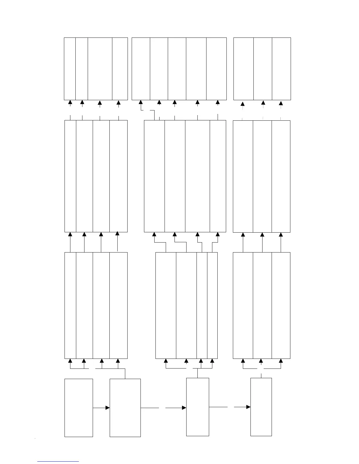
Turn gas supply off.
Set thermostat to call
for heat.
Smart Valve is
powered. (24volt
nominal- 19.5 volts
minimum. 27.5 Max.
Igniter warms up and
glows red.
Turn gas on.
Pilot burner lights
Unplug pilot burner cable
Measure voltage at Terminals 1&2 on
Smart Valve. (19.5 Minimum 27.5 Max.)
Replace Igniter/Flame
sensor assembly
Start
Check
Replace Smart Valve
YES
YES
Check line voltage
Check primary, Aux. & roll out limits
Check Voltage @ transformer
Check induced draft blower operation
Correct line voltage
Correct low voltage
Reset or replace limit
Replace control board
NO
Check pilot to burner alignment.
Correct pilot position
Check igniter continuity with Ohm meter
SMART VALVE DIAGNOSTIC / TROUBLE SHOOTING CHART
PROCEDURE
CTION
Measure voltage @ L1, L2, & GR.
Measure voltage @ Control board GY-25
& R-1
Measure voltage @ Control board molex
plug "OR-49 to BR-21. Must read 0 volts
Check Voltage @ Red & Violet Wires to
ID blower @ Control Board(230 volts)
Check thermostat & wiring
Measure voltage @ Control board
terminals "W" to C 19.5 Min. 27.5 Max.
Repair/replace
thermostat/thermostat
wiring
Check gas valve
Check ingiter
Check gas valve
Check pilot assembly
NO
Verify that pilot is positioned in front of the
burner carry-over
Verify that pilot orifice is free of
obstructions and corectly sized for gas
Check pressure switch operation
Check Voltage @ Yel.-11 at Smart valve
(19.5 volts min. 27.5 Max.)
Replace I.D. Blower
Repair wiring or re-
place pressure switch
YES
NO
Verify that pilot adjustment on gas valve
open and adjusted correctly
Clear obstruction or
replace pilot orifice
Open or adjust gas
valve pilot
NO
NO
NO
NO
NO
NO
NO
NO
NO
NO
YES
NO
 Loading...