5 Installation at Site
30 of 124
Amarex KRT
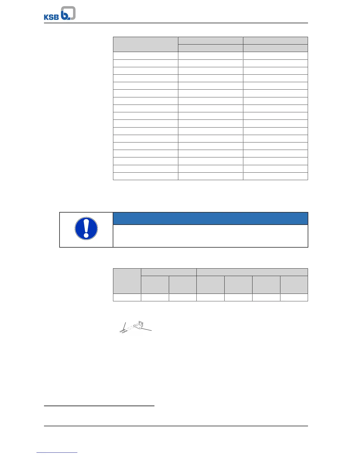
Size Tightening torque M
A
Guide cable tension P
[ft lbf] [lbf]
350-632 15,5
9)
3372
350-633 15,5
9)
3372
350-636 15,5
9)
3372
350-710 15,5
9)
3372
350-713 15,5
9)
3372
400-632 15,5
9)
3372
400-900 15,5
9)
3372
401-710 15,5
9)
3372
401-713 15,5
9)
3372
500-632 15,5
9)
3372
500-634 15,5
9)
3372
500-640 15,5
9)
3372
501-710 15,5
9)
3372
501-900 15,5
9)
3372
600-710 15,5
9)
3372
700-901 15,5
9)
3372
700-902 15,5
9)
3372
5.3.1.4 Fitting the guide rail arrangement
The pump set is guided into the sump or tank along two vertical guide rails. It
attaches itself automatically to the base elbow which has been fitted to the floor.
NOTE
The guide rails are not included in KSB's scope of supply.
Select guide rail materials which are suitable for the fluid handled or as specified by
the operator.
Observe the following dimensions for the guide rails:
Table17: Guide rail dimensions
Nominal
discharge
nozzle
diameter
Outside diameter Wall thickness
10)
[inch] [mm] Minimum
[inch]
Minimum
[mm]
Maximum
[inch]
Maximum
[mm]
200 to 700 3,5 89 0,118 3 0,236 6
Fitting the mounting bracket
Fig.14: Fitting the mounting bracket
1. Fasten mounting bracket 894 to the edge of the sump opening with steel
anchor bolts 90-3.37. Tighten the anchor bolts to a tightening torque of
7.4lbfft [10Nm].
Observe the hole pattern for the anchor bolts. (See outline drawing.)
9) 2 tensioning bolts, value indicated per bolt
10) To DIN 2440/2442/2462 or equivalent standards


 To Next Page