5 Installation at Site
29 of 124
Amarex KRT
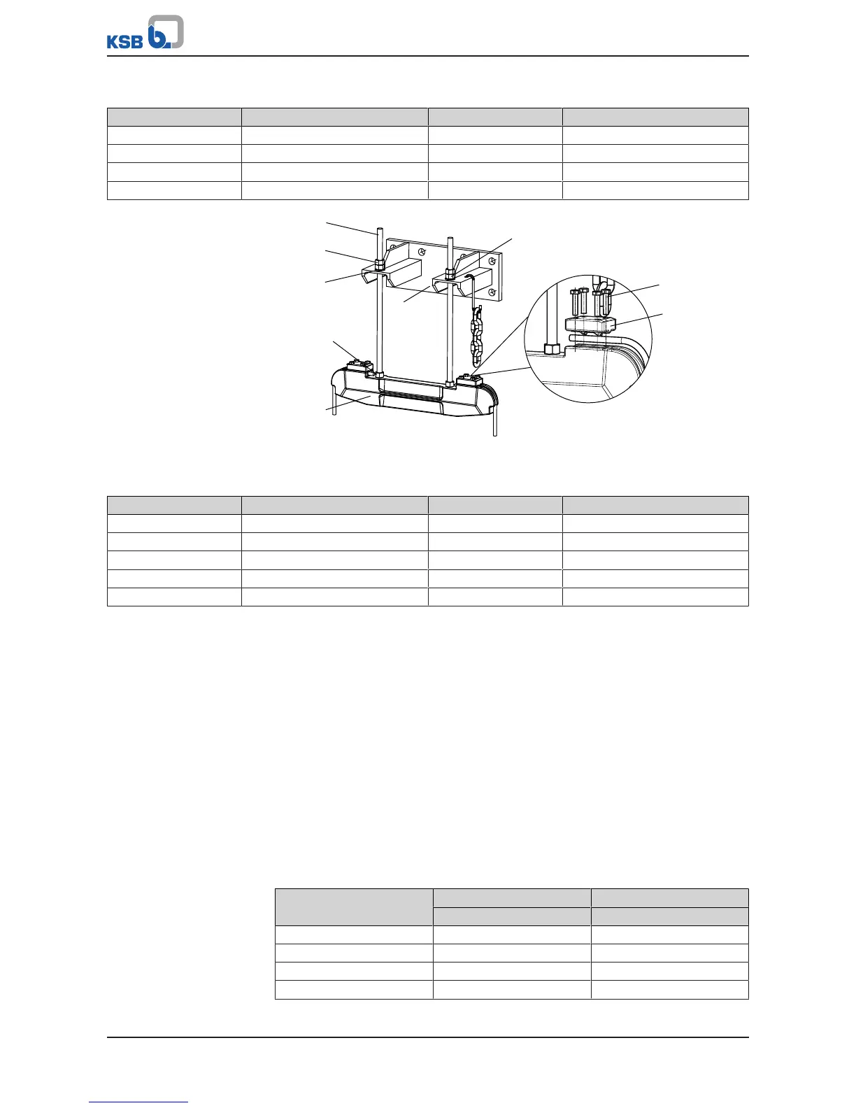
Table14: List of components
Part No. Description Part No. Description
59-18 Hook 572 Guide cable suspension bracket
59-24.01 Guide cable 894 Mounting bracket
90-3.37 Anchor bolt 904 Grub screw
571 Bail 920.36/.37 Nut
Fig.13: Mounting bracket variants for pumps with a nominal discharge nozzle
diameter of DN350, 400, 500, 600, 700
Table15: List of components
Part No. Description Part No. Description
59-18 Hook 894 Mounting bracket
59-24.01 Guide cable 901.36 Hexagon head bolt
550.36 Disc 904 Grub screw
553 Thrust insert 920.36 Nut
572 Guide cable suspension bracket
Inserting the guide cable
1. Lift thrust insert 533, insert one end of the cable and secure it with bolts 901.36.
2. Run cable 59-24.01 around base elbow 72-1 and back again to guide cable
suspension bracket 572. Insert it into thrust insert 533.
3. Manually tension cable 59-24.01 and secure it by means of bolts 901.36.
4. Pull the cable taut by tightening hexagon nuts 920.36 on the upper side of the
mounting bracket.
Refer to the "Guide cable tension" table.
5. Secure the nuts with a second hexagon nut.
6. The loose cable ends at guide cable suspension bracket 572 can either be
twisted into a ring or the end can be cut off.
After length adjustment, tape the ends to avoid fraying.
7. Attach hook 59-18 to mounting bracket 894 for attaching the lifting chain/
lifting rope at a later stage.
Table16: Guide cable tension
Size Tightening torque M
A
Guide cable tension P
[ft lbf] [lbf]
200-631 22,1 2248
250-630 22,1 2248
250-632 22,1 2248
250-900 22,1 2248


 To Next Page