Compact Voice Alarm System
User Manual
14
4. miniVES charger
4.1 miniVES Charger
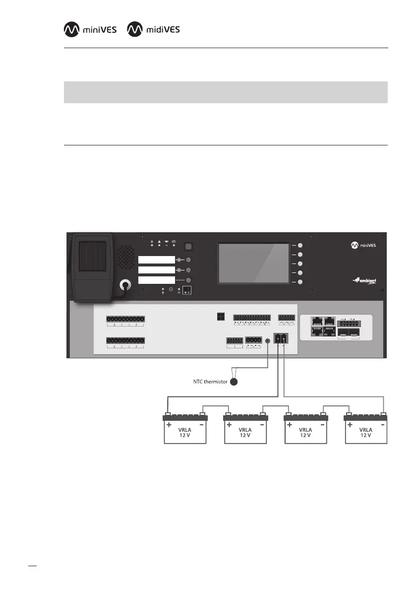
In order to connect the batteries to the charger use the battery cable supplied with the device.
Besure of proper connection (polarity) between batteries and terminals. Lastly connect the thermis-
tor temperature sensor to the “TEMP SENSOR” jack and place it near installed batteries. Onlyunused
and type compliant batteries (same manufacturer, equivalent capacity and voltage, same manufac-
turing date) may be connected.
Fig. 7.
BUS1 BUS2
IN7IN6IN5IN4IN3IN2IN1
+48 VDC BATT
Audio IN Audio OUT
C
LR
C
LR
+24 VDC
150 mA
+48 VDC
350 mA
TEMP.
SENSOR
LINE ALINE BLINE CLINE DHV AUDIO IN
C
H
C
H
C
H
C
H
C
H
LINE ALINE BLINE CLINE DHV AUDIO IN
C
H
C
H
C
H
C
H
C
H
LAN/WANRS485
LANLAN PoE
IN1IN2
BA
FIBER
2
1
OUT3OUT2OUT1
Connection between VRLA batteries, temp. sensor and miniVES Charger module
c
NOTE: It is crucial to connect the batteries to the system before startup.
Once the power supply has been provided, connect loudspeaker lines, logic inputs and
outputs, network devices.
When you make sure all connections have been carried out properly, you can power up the system