Figure 21: System Controller Web User Interface
Power On/Off Slide Switch
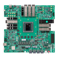
[Figure 4, callout 18]
The VPK180 board power switch is SW13. Sliding the switch actuator from the o to the on
posion applies 12 VDC power from the 2x3 6-pin mini-t power input connector J16 (power
from an external 120 VAC-to-12 VDC power adapter).
IMPORTANT!
Power to the VPK180 is mutually exclusive and only one of the two power connecons
should be powered. Either J16 or all of JP1, JP2, JP3, and JP4 should be used to provide board power.
The four 2x4 8-pin (6+2) ATX power supply PCIe-type connectors JP1, JP2, JP3, and JP4 are
provided for higher power use cases.
• The customer ATX supply chosen must support at least four PCIe (6+2) GPU connecons to
support powering the evaluaon board.
• Only use a single ATX supply to support delivery of 12V to four PCIe GPU (6+2) connectors or
damage might occur.
• When ATX PCIe GPU 6+2 connecons are made, the 6 pin mini-t Jr power brick connecon
and onboard on/o power switch is disabled.
The green LED DS36 illuminates when the VPK180 board power switch is on. See Board Power
System for details on the onboard power system.
Chapter 3: Board Component Descriptions
UG1582 (v1.0) February 21, 2023 www.xilinx.com
VPK180 Board User Guide 66