Do you have a question about the American Eagle 65R and is the answer not in the manual?
Guide to installing air compressor, PTO, pump, and related items.
Diagram detailing electrical connections for the compressor unit.
Details on the compressor's hydraulic system components and operation.
Information on routing the airline and air tank requirements.
Instructions for setting the compressor's pressure switch kick-out and kick-on points.
Diagram of the hydraulic circuit for a single-section pump.
Diagram of the hydraulic circuit for a tandem (two-part) pump.
Diagram of the hydraulic circuit including an auxiliary oil cooler.
Exploded view and parts list for the 65R compressor case assembly (PN 101835).
Detailed assembly illustration of the 65R compressor (PN 101190).
Comprehensive parts list for the 65R compressor assembly (PN 101190).
List of replacement parts for hydraulic system and drive components.
Replacement parts for electrical system and air pressure regulation.
Replacement parts for air filtration and oil filtration systems.
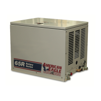
The American Eagle Model 65R Rotary Screw Compressor is a robust and dependable air compressor designed for a variety of operational needs, offering safe and reliable service over many years with proper use and maintenance. This manual serves as a comprehensive guide to ensure the equipment operates at peak performance and longevity. While not intended as a beginner's training manual, it provides solid guidelines for the safe and proper usage of the air compressor, emphasizing the importance of understanding and applying the knowledge contained within for effective operation and maintenance.
A copy of this manual is provided with every air compressor and is stored in a hard plastic manual case installed on the chassis, ensuring it remains with the unit at all times. Throughout the manual, specific signal words—NOTICE, WARNING, and DANGER—are used to highlight important information. "NOTICE" indicates practices not related to physical injury, "WARNING" signifies hazardous situations that could lead to death or serious injury if not avoided, and "DANGER" denotes hazardous situations that will result in death or serious injury if not avoided.
The manual covers various aspects of the Model 65R, including its installation, assembly, and replacement parts. The installation section details the setup of key components such as the pump assembly, PTO assembly, and the compressor itself. For the pump assembly, it notes that it can be installed directly on the PTO or driven by a driveline, recommending consultation with pump manufacturers for specific installation information. A dual or tandem hydraulic pump is suggested when additional hydraulically operated equipment is integrated into the system. PTO assembly requires adherence to the manufacturer's instructions, as vehicle-specific modifications to the transmission cross member and exhaust system may be necessary.
Compressor assembly involves preparing the mounting location by drilling four 1/2-inch diameter holes according to the base pattern. The compressor is then secured using four 3/8-inch x 1.25 GR-5 cap screws, 3/8-inch flat washers, and 3/8-inch nyloc nuts. As the compressor is air-cooled, it is crucial to ensure a clean supply of cooling air to the fan with minimal restrictions and adequate space for proper air circulation.
An optional electric or electronic speed control is essential for maintaining the proper operating speed of the air compressor. This control automatically increases the engine speed from idle to a preset speed when engaged and decreases it when disengaged.
The electrical connections for the compressor involve two wires, red and black, from the air pressure switch. The black wire connects to the vehicle frame or a suitable ground, while the red wire connects to a single-throw toggle switch mounted in a convenient location. The other terminal of this switch connects to a fuse holder and then to a 12-volt power supply. A third wire from the air compressor switch is needed when integrating the speed control into the system.
The hydraulic system comprises a pump, oil reservoir, filters, and hoses. The compressor is equipped with a valve block assembly that controls the flow to the hydraulic motor. A 1/2-inch high-pressure hose connects from the pressure side of the hydraulic pump to the oil cooler inlet. A 3/4-inch minimum low-pressure return line is routed to the oil reservoir. The American Eagle design incorporates a sufficient-sized reservoir that includes proper suction and return filters. The cooler is designed to cool the air compressor efficiently, and an auxiliary oil cooler may be required if additional hydraulically operated equipment is added to the hydraulic system. Pressure on the return line exceeding 200 PSI can damage the filter, cooler, and components of the hydraulic system.
The air system routes air using a 3/4-inch (200 psi) air hose. This delivery line must be free from obstructions. A check valve installed between the compressor and a ten-gallon air tank (minimum) is necessary to maintain proper operation of the air compressor.
The compressor pressure switch is a critical component for regulating air pressure. The manual provides detailed instructions for setting the kick-out and kick-on pressures. The kick-out pressure, which stops the compressor, should be set first, typically between 145 psi minimum and 150 psi maximum. After setting the kick-out pressure, the kick-on pressure, which restarts the compressor, should be adjusted to 115 psi minimum and 120 psi maximum. It is important to cycle the compressor to verify these settings. Turning adjustment screws clockwise increases psi settings, while turning them counterclockwise decreases psi settings.
The manual also includes typical hydraulic circuit diagrams for various configurations, such as a single-section pump, a tandem (two-part) pump, and a compressor with an auxiliary cooler, providing visual aids for understanding the system layout.
For maintenance, the manual lists replacement parts, categorizing them into hydraulic components/drive parts, electrical/air pressure components, and air/oil filter components. This comprehensive list includes items like intake valve kits, seals, valve block assemblies, hydraulic motors, sprockets, belts, oil coolers, pressure switches, wire harnesses, oil temperature gauges, fans, air filters, oil filters, separator filters, synthetic compressor oil, and service kits.
American Eagle reserves the right to change any items, components, or parts deemed necessary for product improvement or commercial/production purposes without immediate mandatory updating of the manual. For technical questions, information, parts, or warranty inquiries, customers can contact American Eagle Customer Service toll-free at 800-321-3741 during business hours (Monday-Friday, 8:00 a.m. - 5:00 p.m. CST) or via email.
| Horsepower | 6.5 HP |
|---|---|
| Tank Size | 60 Gallon |
| Model | 65R |
| Drive Type | Belt Drive |
| Phase | Single Phase |