American Eagle
®
65R Compressor Manual | Page 5
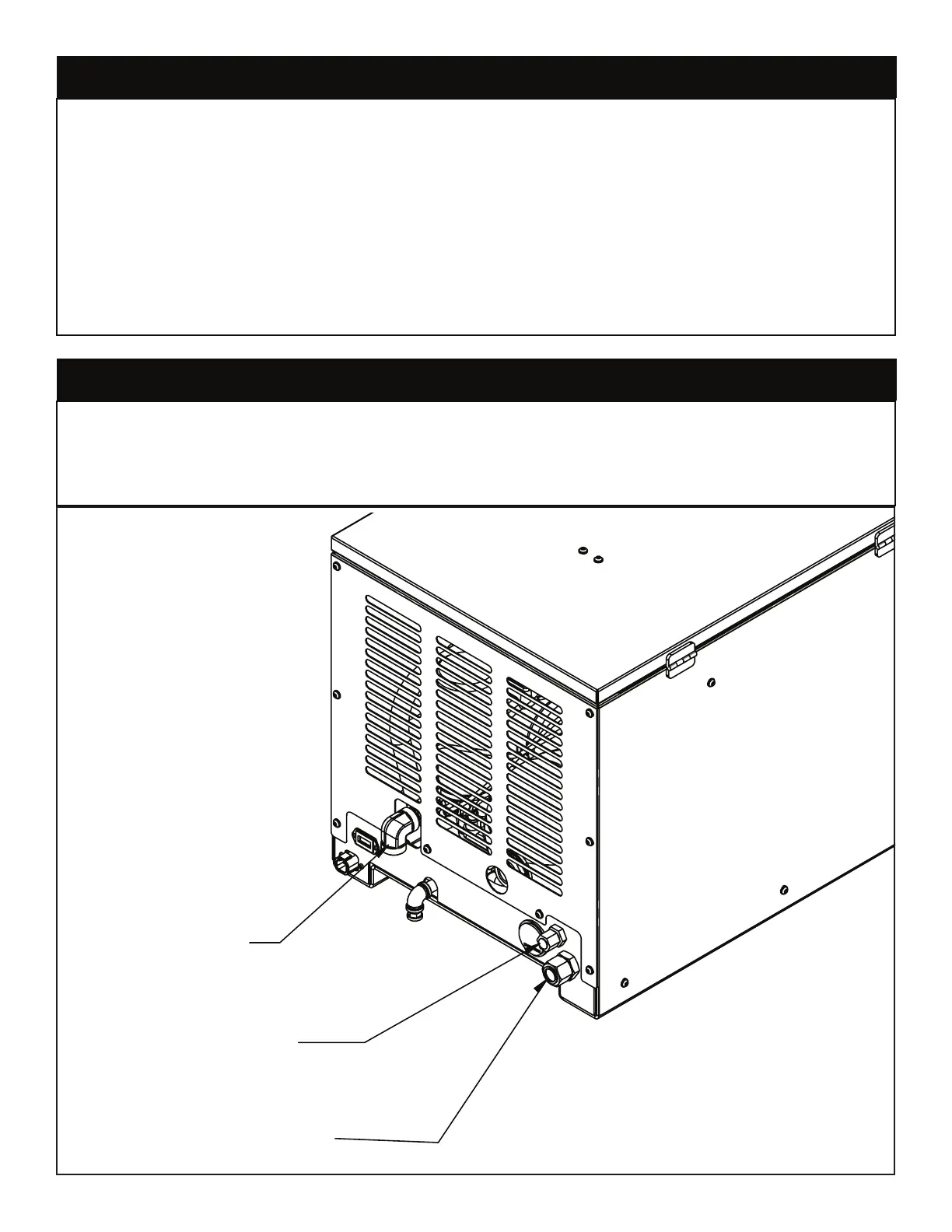
The hydraulic system consists of the pump, oil reservoir, filters and hoses. Installed on the
compressor is a valve block assembly that controls the flow to the hydraulic motor. To this
block, a 1/2” high-pressure hose must be attached. This hose comes from the pressure
side of the hydraulic pump. A 3/4” minimum low-pressure return line is connected to the
oil cooler outlet and is routed to the oil reservoir. American Eagle recommends a sufficient
sized reservoir be provided that includes the proper suction and return filters. The cooler on
the compressor is designed and sized to cool the air compressor efficiently. An auxiliary
oil cooler is required when additional hydraulically operated equipment are added to
the hydraulic system. Pressure on the return line exceeding 200 PSI can and will cause
damage to the filter, cooler, and components of the compressor hydraulic system.
The airline is routed using a 3/4” (200 psi) air hose. This delivery line should be free from all
obstructions. Note: There should be no check valve installed between the compressor
and the air tank. American Eagle recommends the installation of a ten gallon air tank
(minimum) to maintain proper operation of the air compressor.
Hydraulic System
Air System
AIR DISCHARGE
-12 FEMALE NPT
HYDRAULIC PRESSURE
-8 MALE FACE SEAL
HYDRAULIC DISCHARGE
-12 FACE SEAL