Do you have a question about the American Eagle SHD-66 and is the answer not in the manual?
Provides contact details for technical assistance, order placement, and warranty inquiries.
Outlines essential safety measures, protective equipment, and operational guidelines for safe use.
Details the hydraulic system components, pressure ratings, and operational features of the drive system.
Lists the internal components and design features of the air compressor system.
Provides overall model details, weight, dimensions, electrical requirements, and fluid capacities.
Covers essential pre-start checks, general usage, and operational guidelines.
Explains the head unloading system, its operation, and adjustment procedures.
Details the function of the bypass circuit in protecting the compressor from overspeed.
Important operational guidelines, restrictions, and warnings for safe and proper use.
A table outlining recommended maintenance tasks and their service intervals (daily, weekly, monthly, hourly).
General guidance for installing the compressor, pump, and PTO components.
Instructions for connecting hydraulic and air systems, including reservoirs and coolers.
Illustrative diagrams showing typical hydraulic circuits for various configurations.
Exploded view and parts list for the compressor shroud assembly.
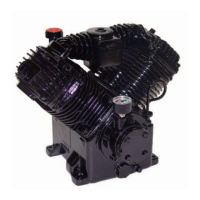
Detailed illustration of the compressor components with reference numbers.
A comprehensive list of parts used in the compressor assembly with part numbers.
Exploded view and parts list for the crankcase, flywheel, and cylinder components.
Exploded view and parts list for the crankshaft, connecting rod, and piston components.
Exploded view and parts list for the valve, manifold, and filter components.
Illustration and parts list for the various tubing connections on the compressor.
List of replacement parts for the hydraulic system, including part numbers and descriptions.
List of replacement parts for the air end and overall assembly, with part numbers.
List of replacement parts for service components like filters, oil, and kits.
A chart identifying common problems, their possible causes, and recommended solutions.
| Brand | American Eagle |
|---|---|
| Model | SHD-66 |
| Category | Compressor |
| Language | English |