Installation 15
Hydraulic System:
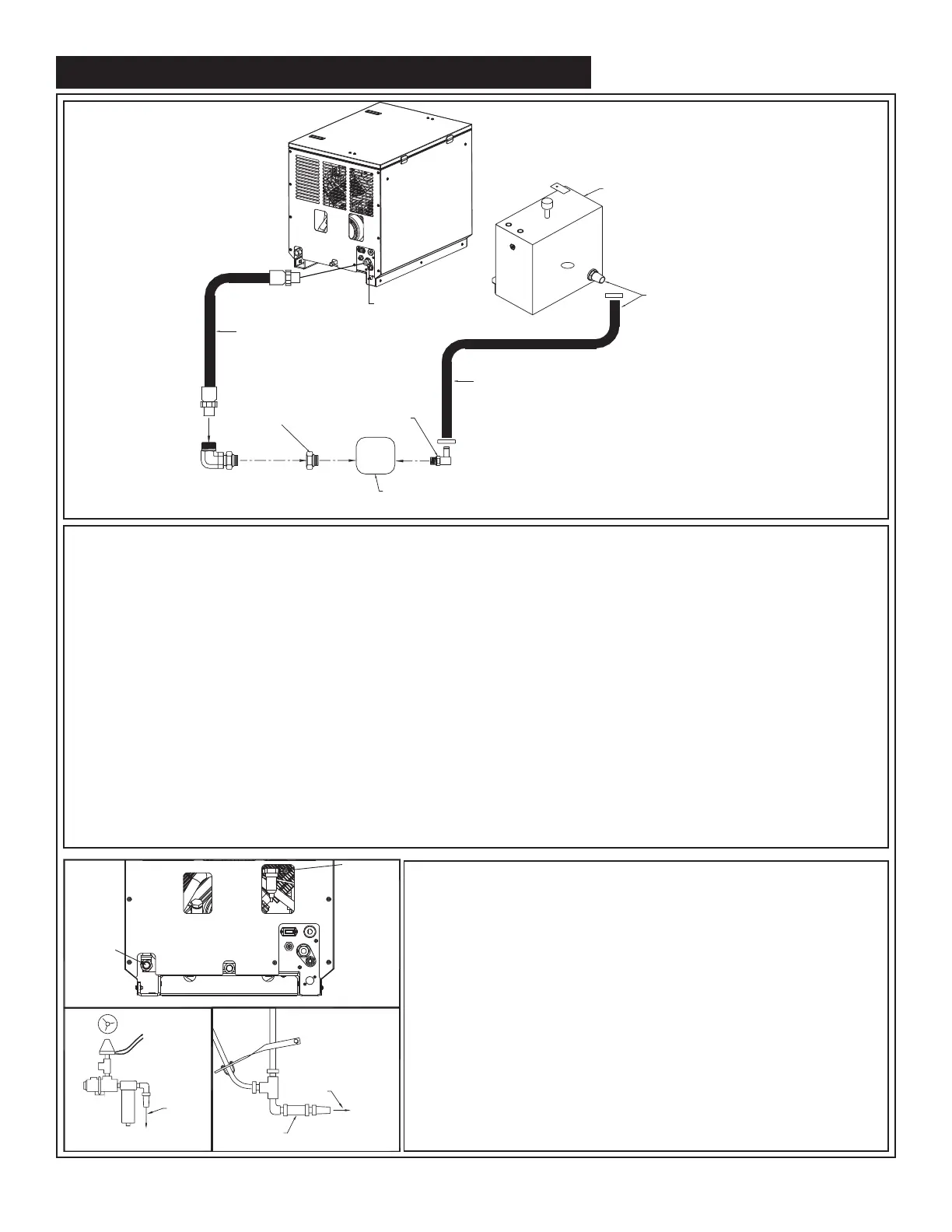
Installed on the compressor are bulkhead fittings to which hydraulic lines are attached. To the
appropriate fitting (see drawing detailing front of compressor), a 1/2” high-pressure hose must be
attached. This hose comes from the hydraulic pumps pressure side. A 1-1/4” hydraulic suction hose
must be installed from the hydraulic reservoir to the hydraulic pump. (See drawing above) Note: For
compressors purchased without a reservoir a 3/4” minimum low-pressure return line is connected to
the hydraulic return fitting and is routed to the oil reservoir through a filter. The case drain line from
the hydraulic motor is also routed to the oil reservoir (DO NOT INSTALL A FILTER ON THE CASE
DRAIN LINE). American Eagle recommends a sufficient sized reservoir be provided which includes
the proper suction and return filters. The cooler on the compressor is designed and sized to cool the
air compressor efficiently. An auxillary oil cooler is required when additional hydraulically operated
equipment are added to the hydraulic system. Pressure on the return line exceeding 200 PSI can
and will cause damage to the filter, cooler, and components of the compressor hydraulic system.
1-1/4” Hydraulic Suction Hose
Length as Required
Connect 1-1/4” Suction Hose
to 1-1/4” Barb Fitting.
Note: There are (2) Locations
that you can Plumb the
Sunction Hose (Side and Bottom)
Stellar
Supplied
Reservoir
1/2” High Pressure
Hydraulic Hose
Length as Required
Motor case drain
routed to hydraulic
reservoir
Hydraulic Pump
Adapter as
Required to
Fit Your Pump
1-1/4” Barb/Adapter
to Fit Your Pump
Air System:
Two (2) airlines must be routed to the air tank for
proper installation. The main airline is routed from the
check valve to the air tank using a 3/4”(200psi) air
hose. This is the main delivery line and should be free
from all obstructions. A 1/4” line is routed from the air
pressure valve to the air tank. This line senses the
pressure in the tank and will engage and disengage
the compressor automatically.
See Detail A
See Detail B
1/4” Hose
3/4” Hose
Air Line
To Air Tank
Check Valve
Air Sense Line
to Air Tank
Detail A Detail B
NO
NC
C
Component Installation Continued...