AMETEK CTS Automotive Immunity Test Generators
V 1.00 13 / 27
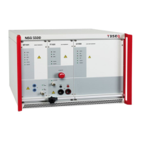
6 Status LED display LD 5550
Flashes when unit addressed
Indicates an error condition
Blinks when the pulse is fired
Lights when pulse 5 is selected
Lights when pulse 7 is selected
7 LD 5550 module
Optional module to generate load dump pulses such as 5a/5b
8 Status LED MT 5511 module
Flashes when unit addressed
Indicates an error condition
Blinks when the pulse is fired
Lights when pulse 2a is selected
Lights when pulse 1 is selected
9 BNC output status LED
Indication of active BNC output e.g. for CCC testing.
10 BNC output connector
To connect an ACC (automotive coupling clamp) for CCC testing.
11 RI LED
RI active indication if selected in the software
12 RI connectors
Input to be selected in the software for certain pulses
13 LED
Indicator there is a test performed at BNC output
14 BNC
Output to perform ICC testing. Activate output in the software.
15 System ground bolt
Central, massive reference ground point of the system.
16 EUT test output
To be connected to an EUT. Carries battery voltage as well as transient pulse.
Output up max +/-60Vdc (depending on dc source) and 100A.
17 Sense Lines
To compensate voltage drop across cabling between NSG 5500 and EUT
 Loading...