AMETEK CTS Automotive Immunity Test Generators
V 1.00 20 / 27
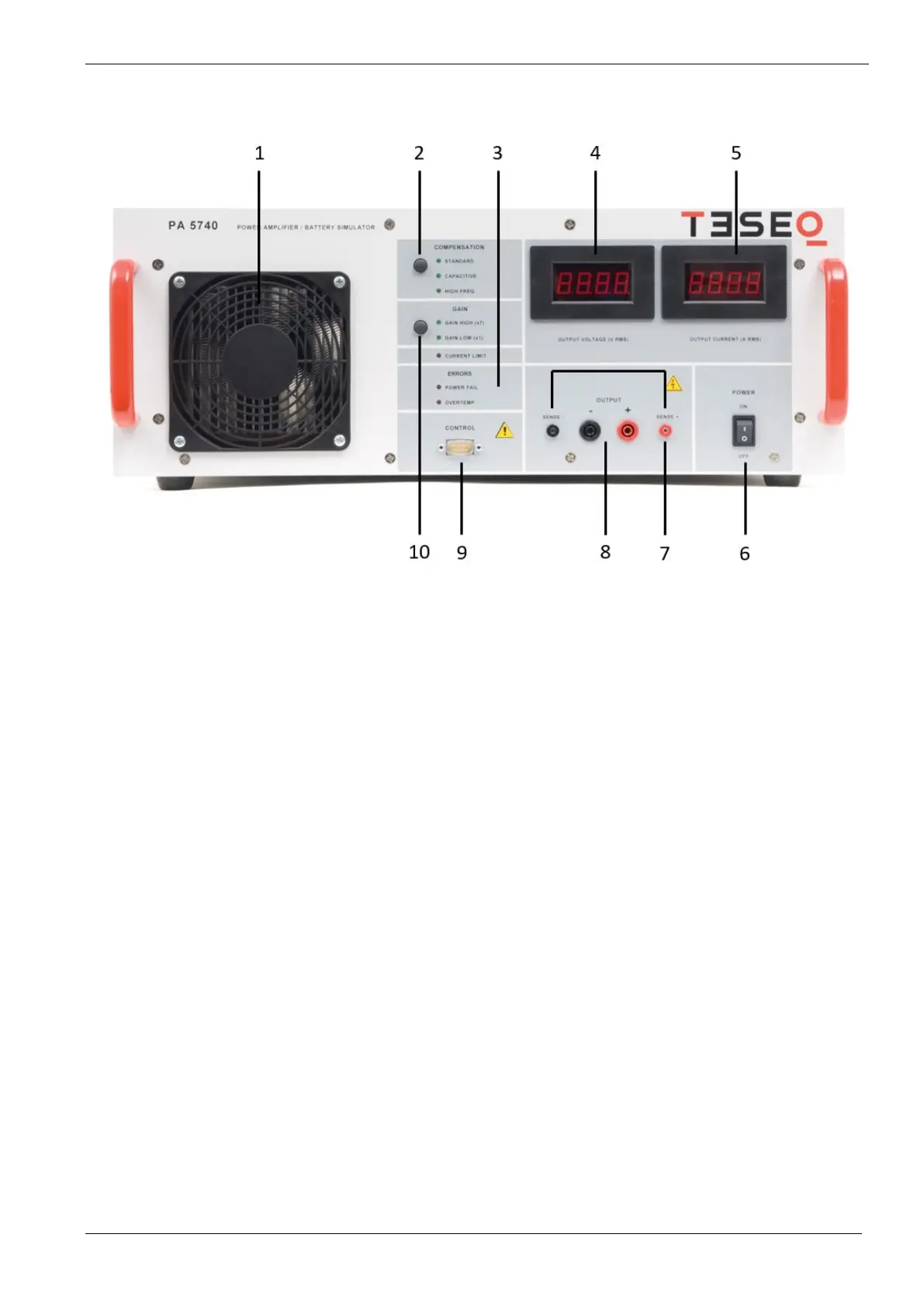
4.5. PA 5740 front view
1 Cooling
Fans and protection covers for cooling. Ensure a proper air flow, keep at least 0.5m to any blocking items
such as walls
2 COMPENSATION modes
Depending in connected DUT and generated signal, changing to a different compendation mode might be
helpful for testing. STANDARD (up to 40kHz) / CAPACITIVE (up to 3kHz) / HIGH FREQ (>40kHz).
Made selection is indicated by LED
3 ERRORS indicators
Shows if an error occurs in the system. Different error indications are SAFETY FAIL, POWER FAIL and
OVERTEMP.
4 Voltage Display
4 digit / seven segment display to show generated dc voltage (RMS)
5 Current display
4 digit / seven segment display to show the current draw (RMS)
6 Power switch
Mains power switch.
7 Sense lines
To compensate voltage drop across cabling between PA 5850 and NSG 5500
8 +/- OUTPUT
To be connected to the NSG 5500 Main / AUX input.
Output max +/-60Vdc / 10A. Do not use front and rear panel output at the same time!
 Loading...