AMETEK CTS Automotive Immunity Test Generators
V 1.00 12 / 27
4. Operating elements, indications, connections 5000-series
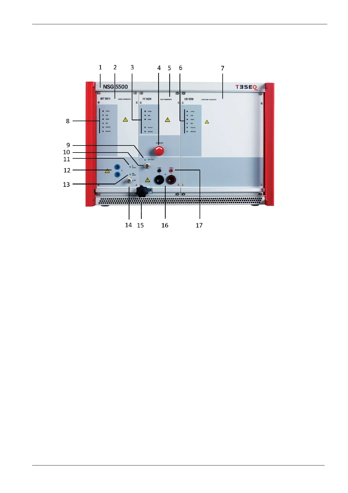
4.1. NSG 5500 front view
1 NSG 5500 chassis
2 MT 5511 module
Optional module to generate micro transient pulses such as pulse 1 and 2a
3 Status LED display FT 5531 module
Flashes when unit addressed
Indicates an error condition
Flashes when 3a pulses generated
Flashes when 3b pulses generated
4 System Stop
Emergency stop to interrupt a running test. Test output is disconnected, neither battery voltage nor
transient pulses are conducted to the output anymore. After activation the NSG 5500 needs to re-power
up (switch off/on mains switch at the back) to properly operate again.
5 FT 5531 module
Mandatory module to generate fast transient pulses (burst 3a/3b). Also includes the 100A coupler
for other transient pulses such as micro pulses and load dump pulses.
Status LED display FT 5531 module
Status LED display LD 5550
Status LED display MT 5511
 Loading...