AMETEK CTS Automotive Immunity Test Generators
V 1.00 17 / 27
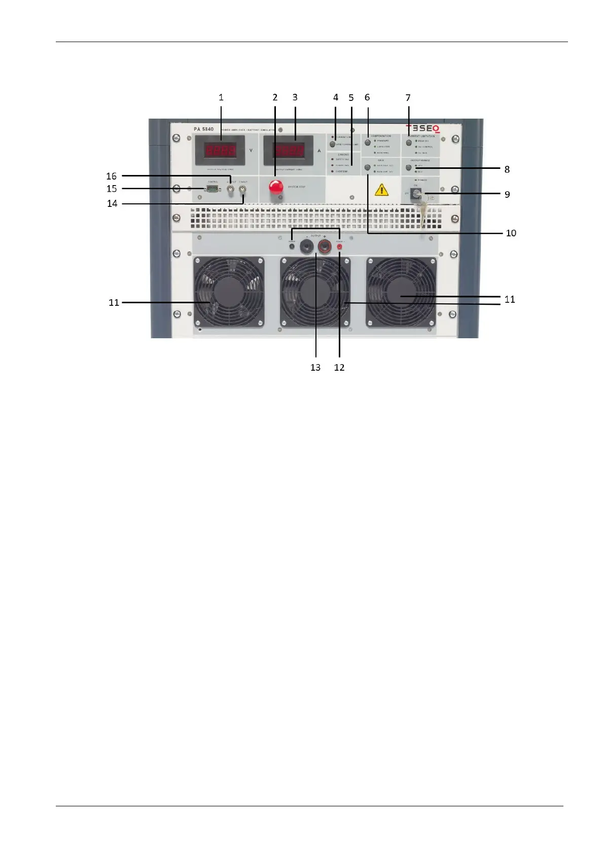
4.3. PA 5840 front view
1 Voltage display
4 digit / seven segment display to show generated dc voltage (RMS)
2 SYSTEM STOP switch
Emergency stop to interrupt a running test. Test output is disconnected.
After activation the PA 5840 needs to re-power up (switch off/on mains switch at the back) to properly
operate again.
3 Current display
4 digit / seven segment display to show the current output (RMS).
4 CURRENT LIMIT
Pushing the button shows the set current limit value (selectable in the software.
Red LED indication shows when the current limiter kicks in.
5 ERRORS indicator
Shows if an error occurs in the system. Different error indications are SAFETY FAIL, POWER FAIL and
OVERTEMP.
6 COMPENSATION MODES
Depending in connected DUT and generated signal, changing to a different compendation mode might be
helpful for testing. STANDARD (up to 40kHz) / CAPACITIVE (up to 3kHz) / HIGH FREQ (>40kHz).
 Loading...