AMETEK CTS Automotive Immunity Test Generators
V 1.00 18 / 27
Made selection is indicated by LED.
7 CURRENT LIMITATION
Select the required current limitation, selection indicated by LED.
PEAK OFF / 3* I CONTROL / 3* I MAX. Selection allows inrush current flow.
8 OUTPUT RANGE
Select between 2 different output voltage ranges, 30V / 60V, selection indicated by LED.
30V range for greater efficiency for 12V and 24V application testing.
9 POWER switch
2 stage power-up switch. First step “ON” activates the control section, second step “START” activated the
power section. Wait a second for switching from “ON” to “START”. Status indication by green LED.
10 GAIN
2 different gains. Gain High (x7) is recommended setting for all 12V, 24V and 48V testing.
GAIN Low (x1) might be used for lower voltage levels. Indication of active gain by LED.
By default select GAIN HIGH.
11 Cooling
Fans and protection covers for cooling. Ensure a proper air flow, keep at least 0.5m to any blocking items
such as walls.
12 Sense lines
To compensate voltage drop across cabling between PA 5850 and NSG 5500.
13 +/- Output
To be connected to the NSG 5500 Main / AUX input.
Output max -15V/+60Vdc, up to 100A current (depending on dc source model).
14 I Input
0-10Vdc analog input to set current limiter value.
Apply an minimum of 1Vdc!
Do not use I INPUT / U INPUT and CONTROL at the same time!
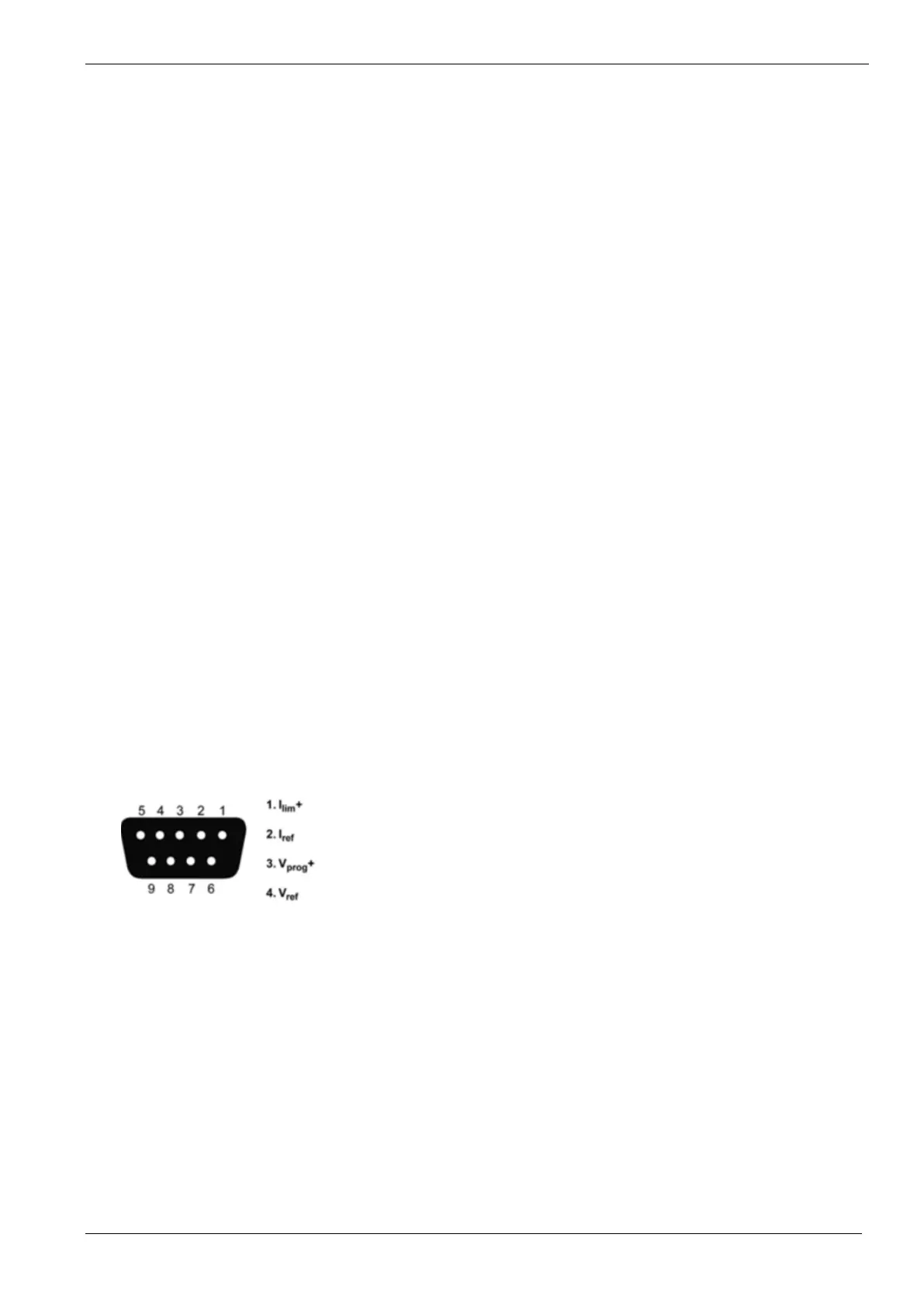
15 CONTROL
9 pins DSub connection to control voltage and current output of the amplifier,
connected to the NSG 5500.
Do not use I INPUT / U INPUT and CONTROL at the same time!
1: Current limiter, 0-10VDC
2: Reference signal of Pin1 (GND)
3: Voltage control, -10 up to +10VDC
4: Reference signal of Pin3 (GND)
Supported bandwith: DC – 500kHz
16 U INPUT
0-10VDC analog input to set a DC battery voltage level.
Gain is according to selection.
Do not use I INPUT / U INPUT and CONTROL at the same time!
 Loading...