M21-400 REV.1.1 DVPLUS DIGITAL VISCOMETER - OPERATIONAL MANUAL
Back Arrow Return to the previous screen.
Home Icon Return to the Main Menu screen.
Spindle Enter Spindle Selection screen.
Speed Enter Speed Selection screen.
End Condition Choose the desired end condition.
QC Limits Choose the desired QC Limit
Run Start Configured Test.
Settings Various instrument settings. See section 2.9
2.5 Spindle Selection
DVPlus LV Viscometers are provided with a set of four spindles and a narrow guard leg. DVPlus RV Viscometers are
provided with a set of six spindles and a wider guard leg. DVPlus HA and DVPlus HB Viscometers come with a set of
six spindles and no guard leg (see Appendix F for more information on the guard leg).
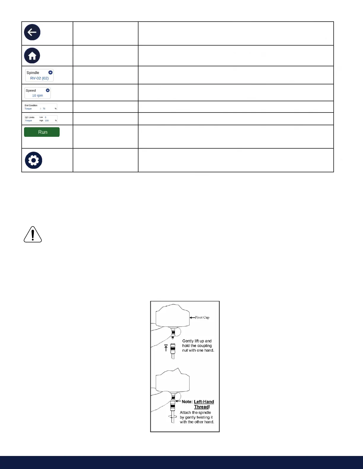
The motor must be OFF whenever spindles are being removed or attached.
DVPlus Viscometers and spindles are oered in two dierent coupling configurations: Threaded or Magnetic.
The threaded spindles are attached to the Viscometer by screwing them onto the coupling nut on the lower shaft
(see Figure 2-5.1). Note that the spindles have a left-hand thread. The lower shaft should be secured and slightly
lifted with one hand while screwing the spindle to the left. The face of the spindle nut and the matching surface on
the lower shaft should be smooth and clean to prevent eccentric rotation of the spindle.
Figure 2-5.1