28 User Manual EN Dansensor® ISM-3
P/N 200114-I
09/2021
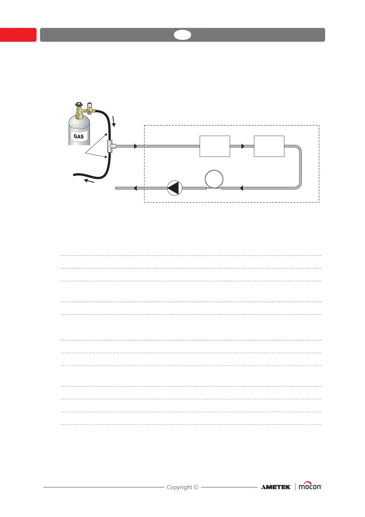
If the ISM-3 is equipped with an internal pump, the gas is sucked from measure point at
atmospheric pressure. When calibrating, the gas is sucked from a gas overflow, to which
approx. 0.5 l/min must be supplied.
Fig. 6. Flow diagram of ISM-3 with pump. Gas overflow for calibration use is shown
Operation and connection
Operation of ISM-3:
Display 4 digit red LED display
Control 4 front keys. Key function is activated when key is released.
Measuring accuracy Better than +/- 1% of the measured value
+/- 1 digit in calibrated measuring range
Measuring range 20.9% - 1ppm (standard) *
* For measuring in other ranges device must be recalibrated - see "Calibration" on page 19 for details
Possible connection to the ISM-3:
Gas supply Gas inlet on the back
Relay Max. 48V, 1A. (COMMON, N.O. and N.C.)
Current output Programmable 0-20 or 4-20 mA, with user-defined scale
(e.g. 0-1%, 10-20.9% or 0-100ppm O
2
).
Voltage output (Option) Programmable 0-10 volt or 2-10 volt with user defined scale
Measure input 10-32VDC external pump control. Consumption 10mA.
RS232C (Option) For serial communication with a PC (for internal use only)
All electrical inputs and outputs, except for the RS232C port, is galvanically separated from
the internal electronics by means of optocouplers and/or a relay.
(for flow indication)
Restriction hose
Gas out
125 ml/min
Pump
Gas in
0,5 l/min
Hoses:
ID = min. 3 mm
L = min. 0.5 m
O
2
sensor
Pressure
sensor