Theory of Operation Sorensen DCS-E Series 3kW Supplies
5-4 M362295-01 Rev D
Monitor signals are available for:
•
Output voltage (calibrated)
•
Output current (calibrated)
•
Operating mode
•
Thermal shutdown
•
OVP status
•
Local/remote programming status
5.2.7 Front Panel Displays and Local Operating Mode Controls
(A1 PCB)
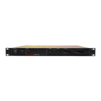
In addition to providing the output voltage and current displays, the front panel has the local
controls for:
•
Output voltage
•
Output current limit
•
OVP set point
•
Output standby (locally-controlled shutdown)
•
Remote/local programming selection
5.3 DETAILED CIRCUIT DESCRIPTIONS
Refer to Section 7 Assembly Schematics for links to the Elgar website to access illustrations
of the following assemblies:
1. AC Input and RFI Filter Circuit (A5 PCB)
2. Input Rectifier and Inrush Limiting Circuit (A6 PCB)
3. PWM, Sync Circuit, Power Transformer Drive Circuit, and Power Transistor Bridge
(A3 PCB)
4. Power Transformer, Output Rectifiers, Output Filter Inductor and Capacitors, and Down
Programmer Circuit (A4 PCB, A7 PCB, A8 PCB, and Power Stage Assembly)
5. Auxiliary Supply, Voltage and Current Control, Programming, and Monitor Circuits
(A2 PCB)
6. Front Panel Displays and Controls (A1 PCB)
Note: When several like components with similar functions are referred to in the circuit
descriptions in this section, a hyphenated numeric format has been used to shorten the
list. For example, C1-3 denotes capacitors numbered 1 through 3, inclusive.

 Loading...


