EasyManua.ls Logo

Ametek Sorensen XG User Manual

Ametek Sorensen XG
381 pages
To Next Page IconTo Next Page
Page #1 background imageLoading...
Page #1 background image
PROGRAMMABLE POWER
M370430-01 Rev B www.programmablepower.com
XG and XTR Family
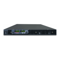
Programmable DC Power Supply
Operating Manual
(firmware v 2.0 and higher)
670 Watts 1700 Watts
Half Rack
Full Rack
6 V to 600 V Models:
6-110
6-220
6-220
8-100
8-187.5
8-200
12-70
12.5-120
12-140
20-42
20-76
20-84
33-25
30-50
33-50
40-21
40-38
40-42
60-14
60-25
60-28
80-10.5
80-19
80-21
100-8.5
100-15
100-17
150-5.6
150-10
150-11.2
300-2.8
300-5
300-5.6
600-1.4
600-2.6
600-2.8

Table of Contents

Questions and Answers:

Ametek Sorensen XG Specifications

General IconGeneral
Output TypeDC
CoolingForced air
Control InterfaceAnalog
Ripple Voltage10 mVrms / 50 mVpp typical
Operating Temperature0°C to +50°C
ProtectionsOVP, OCP, OTP
Output Voltage Range0-5V to 0-600V (depending on model)
Input Frequency47-63 Hz

Summary

Introduction

Features and Options

Details the features and various interfaces of the XG/XTR Family Programmable DC Power Supply.

XG and XTR Models

Lists the XG/XTR 850 Watt series models covered in the manual with their voltage and current ranges.

Front Panel

Illustrates and describes the front panel components of the XG/XTR power supply units.

Rear Panel Connectors on 850 Watt Models

Details the rear panel connectors for the XG/XTR 850 Watt units across different voltage models.

Rear Panel Connectors on 1500 and 1700 Watt Models

Details the rear panel connectors for the XG/XTR 1500 and 1700 Watt units across different voltage models.

Installation

Basic Setup Procedure

Provides a summary of the basic setup steps and references for installing the power supply.

Step 1: Inspecting and Cleaning

Outlines the initial physical inspection and periodic cleaning procedures for the power supply unit.

Step 2: Location and Mounting

Covers rack mounting and benchtop applications, including ventilation requirements.

Step 3: Connecting AC Input Power

Details the procedure for safely connecting the AC input power to the power supply.

Step 4: Selecting Load Wires

Provides recommendations for selecting appropriate load wire sizes based on current carrying capacity.

Step 5: Performing Functional Tests

Describes procedures for performing power-on checks and voltage/current mode operation tests.

Step 6: Connecting Loads

Explains how to connect single and multiple loads to the power supply's DC output.

Step 7: Connecting Remote Sensing

Details the process of connecting remote sense wires to the power supply for accurate load regulation.

Local Operation

Introduction

Overview of local operation and turning on the power supply.

Configuring Settings from the Front Panel

Instructions on using the 9-position mode control and rotary Adjust/Enter control.

Coarse and Fine Adjustment Modes

Explains coarse and fine adjustment modes for setting parameters like voltage, current, and OVP/UVP.

Navigating the Menu System

Describes the general procedure for navigating the XG/XTR menu system.

Display Messages on the Front Panel

Lists display texts used on the front panel to indicate status or mode.

Operating Modes

Details the three operating modes: Constant Voltage, Constant Current, and Constant Power.

Alarms and Errors

Describes conditions that cause alarms and the alarm order of precedence.

Clearing Alarms

Provides methods for clearing triggered, manual, and flash failure alarms.

Using Over Voltage Protection (OVP)

Explains the OVP circuit function and how it protects the load from overvoltage conditions.

Using Under Voltage Protection (UVP)

Details the UVP function, which prevents voltage settings below a specified value.

Resetting the Power Supply

Describes how to perform a soft reset to clear parameters to factory default values.

Using Multiple Power Supplies

Covers operating power supplies in series or parallel for increased voltage or current.

Analog Programming (APG) and Isolated Analog Programming (ISOL)

Introduction

Overview of analog signals for controlling and monitoring the power supply output.

Analog Programming (APG) of Output Voltage and Output Current

Explains how to control output voltage and current using analog input sources.

Remote Programming Options

Details the analog monitor signals available for APG and their corresponding reference lines.

Auxiliary Outputs

Describes the auxiliary outputs providing isolated +5 V and +15 V sources.

Analog Programming (APG) Connector J1

Details the pins and functions of the 18-pin APG connector for sense control and programming.

Making Control Connections

Provides safety precautions and steps for connecting external circuits to APG connectors.

Voltage-Controlled Voltage APG Setup

Instructions for activating and deactivating APG voltage mode using an external voltage source.

Voltage-Controlled Current APG Setup

Instructions for activating and deactivating APG current mode using an external voltage source.

Isolated Analog Programming Mode (ISOL)

Describes the ISOL mode and the AUX Output/ISOL connector functions.

Making ISOL Control Connections

Safety precautions for making connections to the Isolated Analog Programming Connector.

Remote Operation

Introduction

Overview of remote control capabilities using SCPI standard via various interfaces.

Hardware and Connection Setup

Information on setting up hardware for connections to remote interfaces like RS-232, RS-485, USB, GPIB.

Configuring Remote Control Using RS-232

Steps for configuring remote control using the RS-232 interface.

Configuring Remote Control Using RS-485

Steps for configuring remote control using the RS-485 interface.

Configuring Remote Control using the USB Connector

Instructions for setting up the PC to use the USB connection for remote control.

GPIB Connector (Optional)

Details the GPIB interface and its pin description for remote programming.

Ethernet/LAN (ENET) Connector (Optional)

Information on using the Ethernet/LAN connector for remote programming.

Multiple Power Supply Connections to RS-485 Bus

Describes how to connect multiple units to the RS-485 bus for multichannel addressing.

Terminal Configuration

Guides on setting up terminal programs for serial communication with the power supply.

Selecting the Appropriate Communication Port

Details how to select communication ports for remote digital programming and readback.

Status Reporting in SCPI

Explains the status reporting implemented according to the SCPI standard.

Status Byte

Describes the Status Byte register, its bits, and how to read it.

SCPI Error/Event Queue

Details the SCPI error/event queue, its format, and how to query for errors.

Reset Command

Explains the device reset command and its effects on various settings and registers.

Command Line Help System

Provides information on accessing help for SCPI commands and their syntax.

Locking and Unlocking the Front Panel

Describes how to lock the front panel to prevent unauthorized changes.

Auto Sequence Programming

Explains how to execute stored programs and manage dwell time.

Configure Other Protection Mechanisms

Details protection mechanisms like Foldback Protection, Over Temperature Protection, and Loop Protection.

Power Saving Control (Sleep Mode, XTR/XG 1700 W Only)

Explains the Sleep Mode feature for reducing power consumption when the supply is not in use.

Communications Options

INTRODUCTION

Overview of setup and programming for LAN/Ethernet connection for XG/XTR series.

SETTING UP XG/XTR 850 WATT MODELS

Instructions for network administrators to configure the power supply with the MEA option.

Network Topology and Connection

Describes network topologies for single computer and single power supply unit setups.

Setting Up the Computer

Steps to configure the computer's network connection settings for communication.

Software Installations

Guides on installing necessary software like Lantronix DeviceInstaller for ENET option setup.

Configuring the Device Using DeviceInstaller

Details on configuring XG/XTR units using DeviceInstaller software.

Assigning an IP Address to the Power Supply Unit

Steps for assigning an IP address to the power supply unit for network communication.

Selecting ENET as the Communication Port

Instructions to configure the XG/XTR to use the ENET option card as the active communication port.

Establishing Communication with the Power Supply

Steps to establish communication with the power supply using HyperTerminal.

Advanced Section

Covers advanced network topologies involving multiple power supplies.

Network Topology 1: Simple LAN

Describes the simple LAN topology configuration for the ENET option.

Network Topology 2: ENET and RS-485 Bus

Details the topology for connecting units via ENET and RS-485 bus.

SETTING UP XG/XTR 1500 and 1700 WATT MODELS

Information for network administrators on configuring power supplies with the MEB option.

LOCAL AREA NETWORK (LAN) OPTION

Explains the LAN (Ethernet) interface capabilities and setup for programmable functions.

AMETEK LXI DISCOVERY BROWSER

Details the software tool for automatically locating LXI compliant devices on a network.

AMETEK ENETTEST UTILITY

Introduces a utility for sending SCPI commands and receiving responses over Ethernet.

SETTING LAN PARAMETERS

Describes three methods for setting required LAN information on the power source.

SYSTEM COMMANDS

Details system commands that control the system-level functions of the power source.

LXI COMPLIANCE

Describes the implementation of LXI features in the XG power supply.

Calibration and Troubleshooting

Introduction

Overview of calibration procedures, noting it's software-dependent and performed via SCPI commands.

Main Voltage and Current Calibration Principle

Explains gain and offset errors in analog programming and the iterative calibration process.

Calibrating the Output Voltage

Provides procedures for gain and offset calibration of the output voltage.

Calibrating the Output Current

Provides procedures for gain and offset calibration of the output current.

Over Voltage Protection Calibration

Details the procedure for calibrating the Over Voltage Protection (OVP) system.

Non-isolated Analog Programming Calibration

Covers calibration for non-isolated voltage and current monitoring and programming.

Isolated Analog Programming Calibration

Covers calibration for isolated voltage and current monitoring and programming.

Calibrating the Input Voltage APG Signal

Details gain and offset calibration for the input voltage APG signal.

Calibrating the Input Current APG Signal

Details gain and offset calibration for the input current APG signal.

Storing and Loading Calibration Parameters

Recommends saving and reloading calibration parameters to a text file.

Restore Factory Calibration

Instructions to restore factory calibration settings using an SCPI command.

User Diagnostics

Provides operator-level functions for troubleshooting without opening the unit.

Emergency Shutdown

Steps to follow in an emergency situation to shut down the power supply.

Troubleshooting for Operators

General troubleshooting tips for common operating issues.

SCPI Command Reference

SCPI Conformance Information

Details the standards and requirements the power supply conforms to regarding SCPI.

SCPI Command Hierarchy

Illustrates the tree structure of SCPI commands, showing roots, nodes, and leaf nodes.

Using SCPI Commands

Explains the format, syntax, abbreviations, and punctuation of SCPI commands.

Parameter Types

Describes different data types used in SCPI messages: Boolean, Discrete, Numeric, String.

SCPI Command Tree

Provides a visual representation of the SCPI command structure organized as a tree.

SCPI Command Summary

Summarizes SCPI commands supported by the power supply, including IEEE 488.2 commands.

Error Messages

Error Messages

Explains how errors are placed in a queue and the conditions for clearing the error queue.

Command Error List

Lists IEEE 488.2 syntax errors detected by the instrument's parser.

Execution Error List

Details errors detected by the instrument's execution control block.

Device-Specific Error List

Lists errors not related to command, query, or execution, possibly due to hardware/firmware issues.

Query Error List

Describes errors related to output queue control and message exchange protocol problems.

Specifications

Table C-1 XG/XTR 850 Watt Electrical Specifications

Provides detailed electrical specifications for XG/XTR 850 Watt models across various voltage ranges.

AC Line Input Specifications for XG/XTR 850 Watt

Details the required AC input voltage and frequency specifications for the 850 Watt models.

Table C-2 XG/XTR 1500 Watt Electrical Specifications

Provides detailed electrical specifications for XG/XTR 1500 Watt models across various voltage ranges.

AC Line Input Specifications for XG/XTR 1500 Watt

Details the required AC input voltage and frequency specifications for the 1500 Watt models.

Table C-3 XG/XTR 1700 Watt Electrical Specifications

Provides detailed electrical specifications for XG/XTR 1700 Watt models across various voltage ranges.

AC Line Input Specifications for XG/XTR 1700 Watt

Details the required AC input voltage and frequency specifications for the 1700 Watt models.

Common Specifications for All Models

Lists common performance specifications applicable to all XG/XTR models.

Environmental Specifications (Indoor use)

Specifies operating and storage conditions like temperature, humidity, and altitude.

Mechanical Specifications

Provides dimensions and weight for XG/XTR 850W and 1500/1700W models.

Regulatory Approvals

Lists safety and EMC compliance standards met by the power supply.

Rack Mount Options and Installation Instructions

Rack Mount Kit Options

Describes available rack mounting options and their part numbers.

XG/XTR Single (Half Rack) and Dual (Full Rack)

Illustrates rack mount kit options for installing units into half and full racks.

Location Requirements

Specifies environmental conditions for installing the power supply.

Mounting Option A: 1U Rails

Provides instructions for installing the power supply using 1U flanged rails.

Mounting Option B: Manufactured Slides from Jonathan® Engineered Solutions

Guides on selecting and installing manufactured slides for easy power supply access.

Related product manuals