35
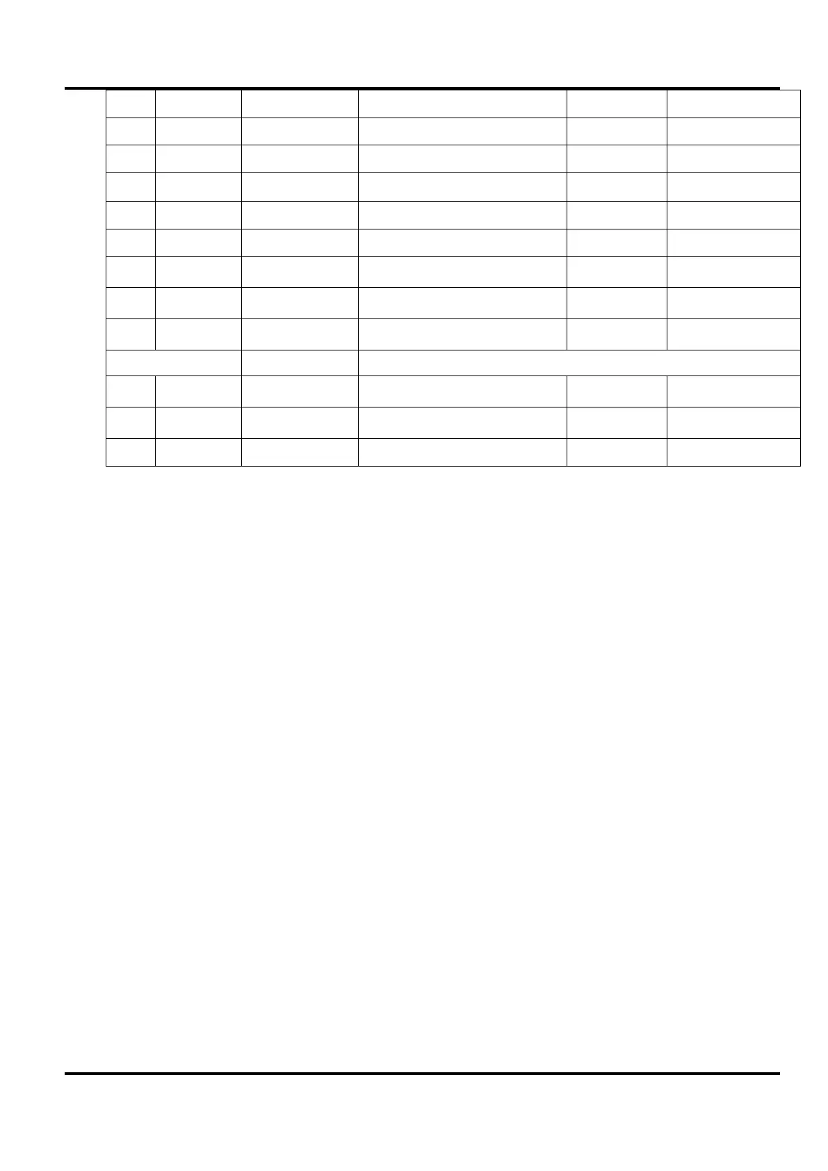
2. 0V Cal count 0V ± 2mV DVM
3. Max V, 1A Cal count 60V ±2mV DVM
4. Max V, 1A O/P volts Display = DVM DVM
6.
Display = 0 -
7. 4V, 0A Cal count 0mA ± 2mA milli-ammeter
8. 4V, 0A O/P amps Display = milli-ammeter ±2mA milli-ammeter
9. 4V, 10A Cal count 10A ±10mA Ammeter
10. 4V, 10A O/P amps Display = ammeter Ammeter
11. O/P off
- - Stores and exits
Powerflex Adjustment
This is factory set and would not normally need to be readjusted during routine calibration.
However, if a component in that part of the circuit has been changed, proceed as follows. These
adjustments are on the Control PCB mounted behind the rear panel, accessed by removing the
top cover which is secured by 6 screws.
WARNING!
When the instrument is connected to its supply the removal of covers is likely to expose live parts.
Any adjustment of the opened instrument under voltage shall be avoided as far as possible and, if
inevitable, shall be carried out only by a skilled person who is aware of the hazard involved. Note
in particular that the large heatsink in the centre of the Main PCB is at a hazardous voltage.
VR213/VR215 are the adjustments for OUTPUT 1 and VR13/VR15 are for OUTPUT 2; in both
cases these potentiometers can be found close to the current shunt heatsink.
Set the PSU to maximum volts and current.
Set the load to 7.35A and switch on.
Adjust VR13/213 so that the UNREG led just comes on.
Set psu voltage to 22V.
Set the load to 20.00A.
Adjust VR15/215 for 21.1X volts (UNREG led should be on).
These adjustments are most easily performed using an electronic load.

 Loading...
