50 Amico Pipeline
Appendix M
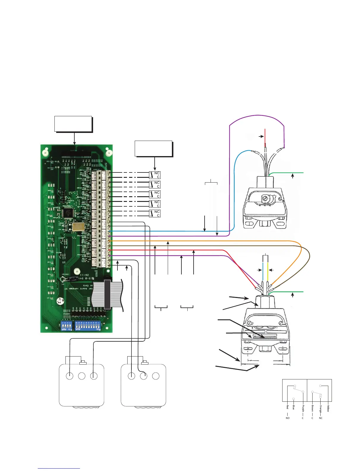
Wiring Diagram Pressure Switch Connection to a Master Alarm
Red
Green
(for Ground)
Master
Module
Blue
e l p r u P
NO
C
l a n g i S m r a l A w o L
Source
Equipment
C NO NCC NO NC
e g n a r O
n w o r B
NC
C
d e R
e l p r u P
NO C
l a n g i S m r a l A w o L
l a n g i S m r a l A h g i H
C
Switch for
High Alarm
Switch for
Low Alarm
Note: There are 2 NIT switches, one for high alarm and one for low alarm.
NO
w o l l e Y
e u l B
Green
(for Ground)
not required
2 - 1/2”
3 - 1/2”
3/4” NPT Conduit
Connection
Circuit No. 1
Calibrated Dial
1/4” NPT
Gas Service
Connection
wiring code
Ground - Green
Common - Purple
Normally Closed -Red
Normally Open -Blue
Circuit #1 for Low Circuit #2 for High
Common - Purple Common - Brown
Normally Closed - Blue Normally Closed - Orange
Normally Open - Red Normally Open - Yellow
Circuit No. 1 Circuit No. 2
Red
Blue
Purple
Brown
Orange
Yellow
NO
C
C
NC
Vacuum
Gas
(OXY, AIR, N
2
O, CO
2
)
Nitrogen
wiring code
Six Leads
18” Long (Approx.)
9/32” x 5/8”
Mounting
Hole (Typ.)
Circuit No. 2
Calibrated Dial
NOTE: There are 2 NIT switches, one for high alarm and one for low alarm.