EasyManuals Logo

Ampac LoopSense Installation And Commissioning Guide

Default Icon
54 pages
To Next Page IconTo Next Page
To Previous Page IconTo Previous Page
Page #29 background imageLoading...
Page #29 background image
Page 25
LOOPSENSE EN54
INSTALLATION & COMMISSIONING
10. Adding Control and Monitoring Facilities
The internal communications connector CN10 provides RS485 serial communications to internal
Add-Ons. CN10 on the Main Card cables to CN1 or 2 on the internal Add-Ons and TB1/1, 2, 3
cables to CN1 or 2 on the remote cards.
10.1 8-Way Relay Board
The Relay Board provides 8 programmable relays with 30VDC 1 Amp voltage free change over
contacts for control or monitoring purposes and comes fitted for internal or external FACP use.
The functionality and programming of the relays is similar to the relays on the main board of the
FACP. By default the relays default to Common Alarm functionality.
Protection
All terminal points are protected.
The board switches the relays as determined by the panel. The relays can be controlled by:
Zones going to alarm
Zones going to fault
Zones Disabled
Reset relay is activated for 3 seconds when reset depressed
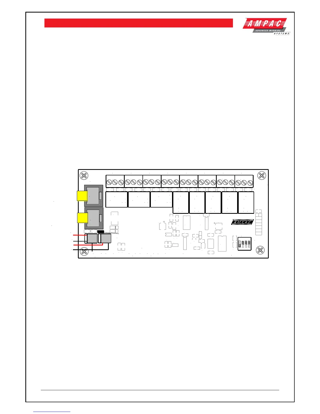
Internal Relay Board
U4
CN5
RL8
RL7
RL6
RL5
RL4
RL3
RL2
RL1
D4
X1
U5
U3
U2
U1
TB8
TB7
TB6
TB5
TB9
TB4
TB3
TB2
TB1
RN3
RN2
RN1
R5
R4
R2
R1
Q4
L2
L1
D3
C14
C12
C11
C10
C9
C8
C7
C6
C5
C4
C2
C1
U6
M4
C3
C13
SW1
D2
M5
M6
M7
M8
M9
M10
M11
M12
M13
M14
M15
M16
M17
M18
M19
R3
R6
TB10
TH1
TH2
TH4
0V
0V
+27VDC
+27VDC
EXTERNAL POWER
rev.1
A
B
COM
COMMS
LK1 = EOL TERMINATION
///
NO NC
C
///
NO NC
CC
NCNO
///
C
NCNO
///
///
NO NC
C
C
NCNO
///
///
NO NC
C
///
NO NC
C
O/P 8
N/C
COMN/0
O/P 7
N/C
COMN/0
O/P 6
N/C
COMN/0
O/P 5
N/C
COMN/0
O/P 4
N/C
COMN/0
O/P 3
N/C
COMN/0
O/P 2
N/C
COMN/0
O/P 1
N/C
COMN/0
302-770
TB1-TB8
A
B
COM
COMMS
ADDRESS SW
POWE R
+27V
0V
CN1
CN2
CN4
CN3
27V
In
Out
RS485 Control
in From the Main
Board or CN2 of
Previous Board
RS485 Control
Out to Next
Board or Link 1
EOL is Applied
1 2 3 4
ON
C16
Figure 12: Internal 8 Way Relay Board PCB Layout
Remote Relay Board
In the remote version the Comms In and Out Terminal Block TB9 is cabled to the RS485 Comms
terminal block TB1/1, 2, 3 on the Main Board and can be installed up to 1.2kms from the FACP.
Note: Can be powered from the panel or an external 27 volt source.
Communications Connections
Terminal
Function
1
RS485+
Communications In
2
RS485-
3
Shield
4
RS485+
Communications Out
5
RS485-
6
Shield

Table of Contents

Other manuals for Ampac LoopSense

Questions and Answers:

Question and Answer IconNeed help?

Do you have a question about the Ampac LoopSense and is the answer not in the manual?

Ampac LoopSense Specifications

General IconGeneral
BrandAmpac
ModelLoopSense
CategoryControl Panel
LanguageEnglish

Related product manuals