LOOPSENSE EN54
INSTALLATION & COMMISSIONING
10.7.3 Printer Connections and Jumper Link Settings
Mounted on the back of the printer mechanism is the PCB that carries the;
Connectors for interconnection to the BRD82ZICC,
Jumper links required to set the programmed print modes; and
Printer 5 volt DC Power Supply.
R5
R6
C14
R7
C15
C16
C18
C8
C17
C7
C19
C21
D2
R9
T1
R8
C3
C20
C4
C22
R11
J7
J6
R10
C5
T2
C13
C12
X1
J1
J3
R1
C9
R2
D1
R4
R3
C1
C2
U1
U2
U3
U4
U6
C6
U7
U8
T4
T3
U5
J2
UP-ATHZP
VER:CC 2002.1
J1 OPEN ESC Command Set
CLOSE UP Command Set
J2 OPEN ASCII Char Mode
CLOSE Chinese Mode
J3 OPEN UP-A Direction
CLOSE UP-T Direction
U9
Connector to Print Head
Connector to
Front Panel
LED & Switches
Connector to BRD82ZICC
5V Power Supply
+ -
J7 Select 12X12 (Pins 1/2) or 15X16 (Pins 2/3) Chinese Characters
Figure 28: PCB Layout
Jumper Settings
Selects ASCII Character Printing Mode
Selects Chinese Character Printing Mode
Select Printing by Contrary Direction
Select printing in the Normal Direction
Insert the Shorting Clip Between Pins
1 and 2
Insert the Shorting Clip Between Pin 2
and 3
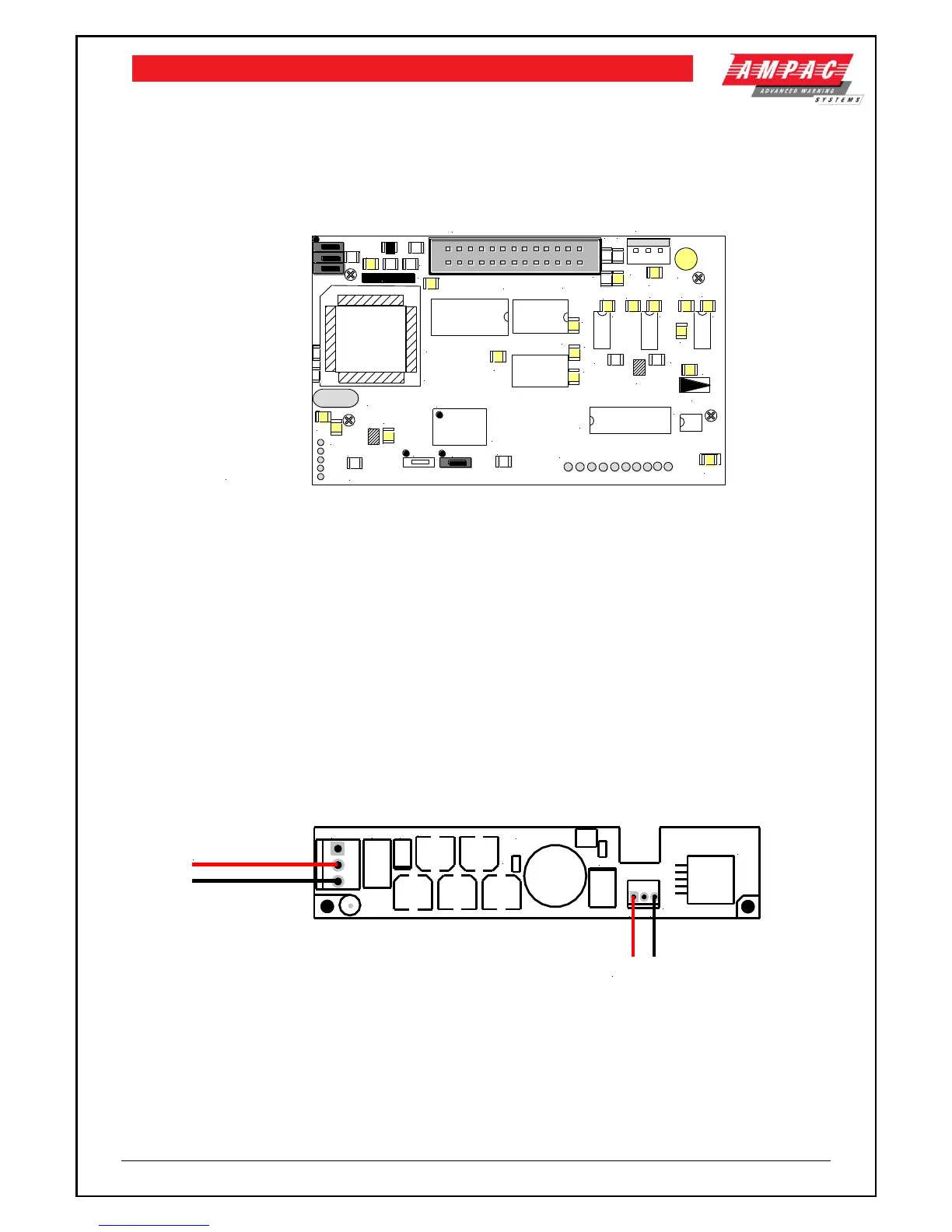
10.7.4 Printer 5 Volt Power Supply (BRD42PVCB1)
27 volts DC is taken from BRD82ZICC and fed to CN1 of the 5volt Printer Power Supply Board. It is
this board that drops this voltage from 27volts to 5volts for use by the Printer.
+27V
0V+V
0V 0V
BRD42PVCB1-
C4
C3
D2
D1
L1
CN1
C1
C2
C5
C6
C7
TH1
U1
CN2
To Printer (5V)
27VDC IN
Figure 29: Printer Power Supply Board Layout