Ampcontrol Pty Ltd – ABN 28 000 915 542
HPB USER MANUAL
HPBB012 Version 9 – March/2020
Uncontrolled Copy - Refer to Ampcontrol Website for Latest Version
APPROVED FOR EXTERNAL DISTRIBUTION
– PROPERTY OF AMPCONTROL PTY LTD
– NOT TO BE
REPRODUCED IN PART
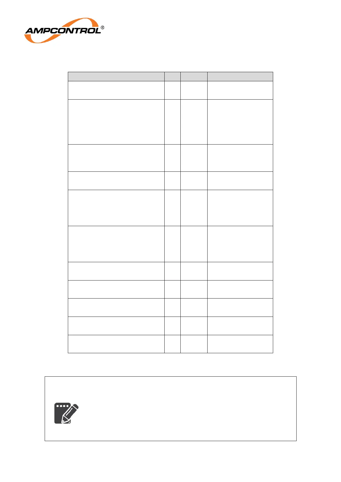
Table 3: Low Voltage Signals
Single core screened
# Screen = 0V
Four core screened
# Screen = 0V
Two core screened
# Screen = 0V
Two core screened
Screen = Earth
Three core screened
Screen = Earth
Current Protection Transformers
Two core screened
Screen = Earth
Local Stop Button
(digital input)
* Two core screened
Screen = Earth
Lock Switch
(digital input)
* Two core screened
Screen = Earth
Reset Switch
(digital input)
* Two core screened
Screen = Earth
Start Switch
(digital input)
* Two core screened
Screen = Earth
Motor Contactor Aux Contact
(digital input)
* Two core screened
Screen = Earth
# The 0V is internally connected to the HPB Relay’s earth (Pin 7).
The screen therefore must NOT be earthed at any other point.
* The HPB Relay’s digital inputs could alternatively be run in a
screened multicore cable (Separate cable for each HPB in multiple
installations).