Chapter 3 Hardware
32 Reference Manual CoreModule 420
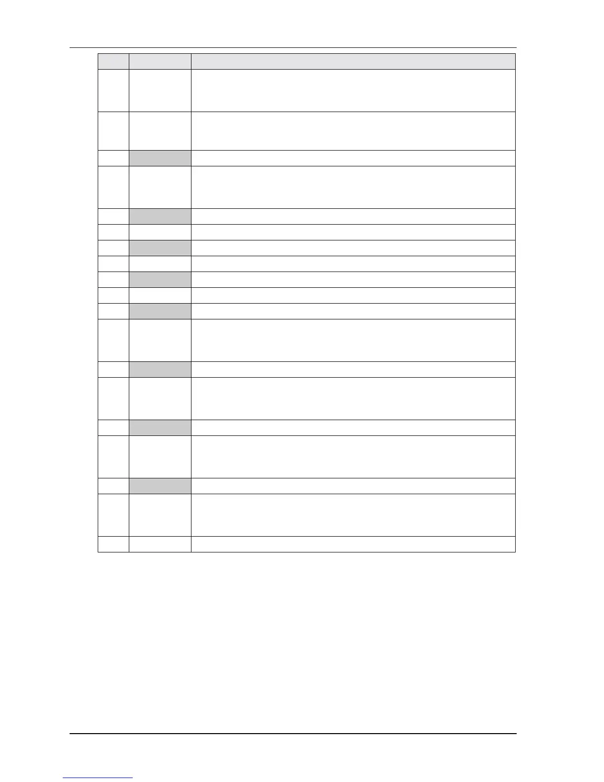
Pin # Signal Description
8
SLIN
STEP
Select In – This output signal is used to select the printer. I/O pin in ECP/EPP
mode.
Step – Low step pulse for each track-to-track movement of the head.
9PD3
RDATA
Parallel Port Data 3 – This pin (0 to 7) provides parallel port data signals.
Read Data – Raw serial bit stream from the drive for read operations.
10 GND Digital Ground
11 PD4
DskChg
Parallel Port Data 4 – This pin (0 to 7) provides parallel port data signals.
Disk Change – Senses the drive door is open or the diskette has been changed
since the last drive selection.
12 GND Digital Ground
13 PD5 Parallel Port Data 5 – This pin (0 to 7) provides parallel port data signals.
14 GND Digital Ground
15 PD6 Parallel Port Data 6 – This pin (0 to 7) provides parallel port data signals.
16 GND Digital Ground
17 PD7 Parallel Port Data 7 – This pin (0 to 7) provides parallel port data signals.
18 GND Digital Ground
19 Ack*
DS1
Acknowledge* – This is a status output signal from the printer. A Low State
indicates it has received the data and is ready to accept new data.
Drive Select 1 – Selects floppy drive 1.
20 GND Digital Ground
21
Busy*
MTR1
Busy* – This is a Status output signal from the printer. A High State indicates
the printer is not ready to accept data.
Motor Control 1 – Selects or enables the motor on floppy drive 1.
22 GND Digital Ground
23 PE
WDATA
Paper End – This is a status output signal from the printer. A High State
indicates it is out of paper.
Write Data – Encoded data to the drive for write operations.
24 GND Digital Ground
25 Slct
WGATE
Select – This is a status output signal from the printer. A High State indicates
it is selected and powered on.
Write Gate – Signal to the drive to enable current flow in the write head.
26 Key/NC Key Pin/Not Connected
Notes: The shaded area denotes power or ground. The signals marked with * indicate active low.