Chapter 3 Hardware
CoreModule 420 Reference Manual 43
• Watchdog Code examples – Ampro has provided source code examples on the CoreModule 420
Doc & SW CD-ROM illustrating how to control the WDT. The code examples can be easily
copied to your development environment to compile and test the examples, or make any desired
changes before compiling. Refer to the WDT Readme file in the Miscellaneous Source Code
Examples subdirectory, under the Support Software menu on the CoreModule 420 Doc & SW
CD-ROM.
Power Interface (J7)
The CoreModule 420 requires one +5 volt power source and uses a 10-pin header with 0.1” spacing.
When the +5 power drops below ~4.0V, a low voltage reset triggers activating a system interrupt.
The power input connector (J7) supplies the following voltage directly to the module:
• 5.0VDC +/- 5% @ 1.35 Amps
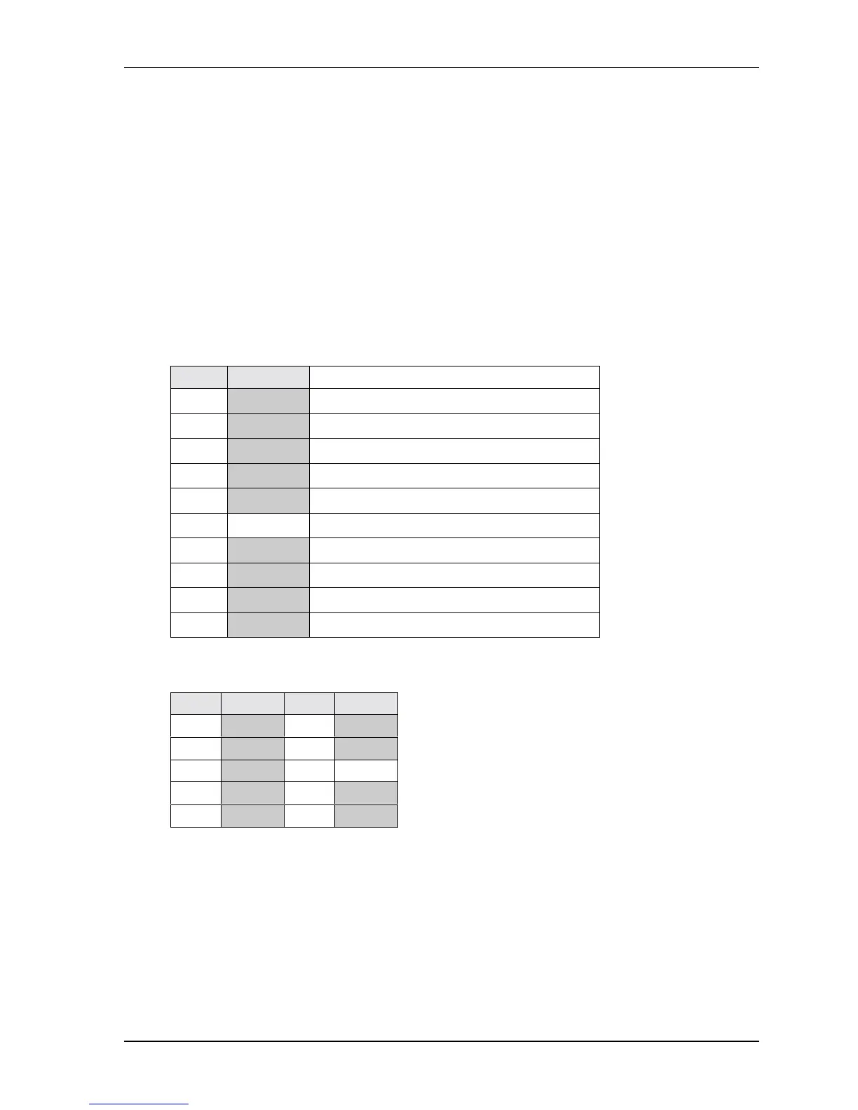
Table 3-19 gives the signals for Power supply pin outs.
Table 3-19. Power Interface Pins/Signals (J7)
Pin Signal Descriptions
1 GND Ground
2 +5V +5 Volts
3 Key/GND Key Pin on connector/Grounded on board
4 +12V +12 volts routed to PC/104
5 GND Ground
6 NC Not connected
7 GND Ground
8 +5V +5 Volts
9 GND Ground
10 +5V +5 Volts
Note: The shaded area denotes power or ground.
Table 3-20. Power Interface Pin Arrangement (J7)
Pin # Signal Pin # Signal
1 GND 2 +5V
3 GND 4 +12V
5 GND 6 Key/NC
7 GND 8 +5V
9 GND 10 +5V
Note: The shaded area denotes power or ground.