Chapter 3 Hardware
CoreModule 420 Reference Manual 33
Serial Ports (J3, J9, J13, J14)
The Atlas CPU and Super I/O chips each contain the circuitry for two of the four serial ports. The Atlas
CPU provides serial port 1 (J3) and serial port 2 (J9) through the two independent 10-pin connectors.
The Super I/O chip provides serial ports 3 (J13) and 4 (J14. The serial ports support the following
features:
• Programmable word length, stop bits and parity
• 16-bit programmable baud rate generator
• Interrupt generator
• Loop-back mode
• 16-bit FIFOs for each port
• Ports 1 and 2 are supported by the STPC Atlas processor and are 15540 compatible
♦ Serial 1 (J3, COM1) supports RS232/RS485 and has full modem operation
♦ Serial 2 (J9, COM2) supports RS232/RS485 and has full modem operation
• Ports 3 and 4 are supported by the Super I/O Controller and are 16550 compatible
♦ Serial 3 (J13, COM3) supports RS232 with full modem support
♦ Serial 4 (J14, COM4) supports RS232 with full modem support
NOTE The RS232/RS485 mode for Serial Port 1 (COM1) and Serial Port 2
(COM2) are selected in BIOS Setup Utility. The RS485 terminations
for Serial Port 1 (COM1) and Serial Port 2 (COM2) are selected using
jumpers (JP1 and JP2) on the board instead of the BIOS Setup Utility.
However, the RS232 mode is the default selection for either
Serial Port 1 or 2 (COM1 or COM2).
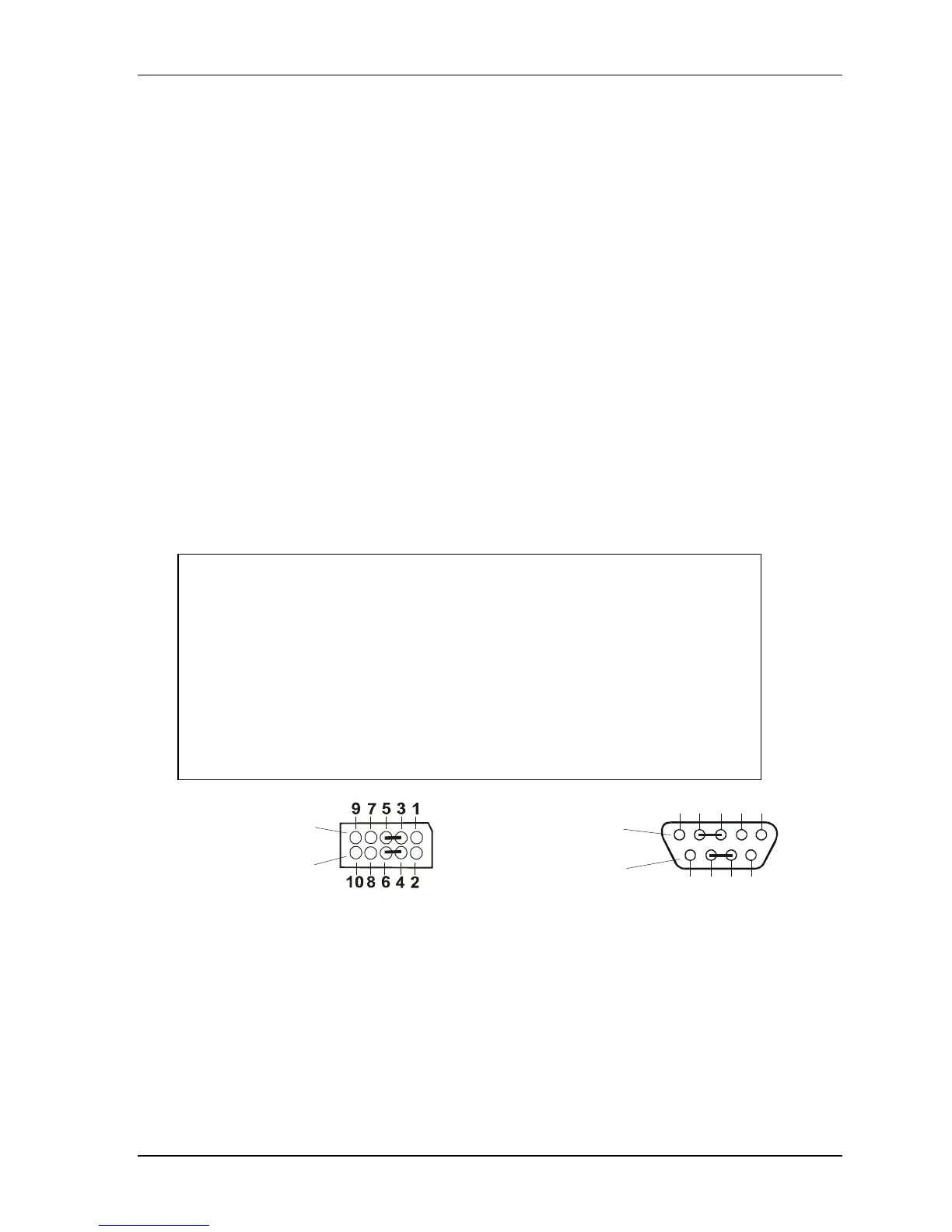
To implement a two-wired RS485 mode with either Serial Port (1 or 2),
you must tie pins 3 (RX Data –) to 5 (TX Data –) and pins 4 (Tx Data
+) to 6 (Rx Data +) at Serial Port 1 or 2 (J3 or J9) for the two-wire
interface. Alternatively, you may short the equivalent pins on the DB9
connector attached to respective serial port, as shown in Figure 3-1.
Or
Serial Ports (J3, J9)
(COM1 or COM2)
Side View
Standard DB9 Serial
Port Connector (Female)
Rear View
5
4
32
1
987
6
CM420RS485jump
Figure 3-1. Serial 1 to RS485 Conversion
Table 3-12 provides the signals for the corresponding pins of the two independent serial interface ports
(Serial 1 & 2) and Table 3-13 provides the signals for the corresponding pins of two independent serial
interface headers (Serial 3 & 4).