Chapter 3 Hardware
40 Reference Manual CoreModule 420
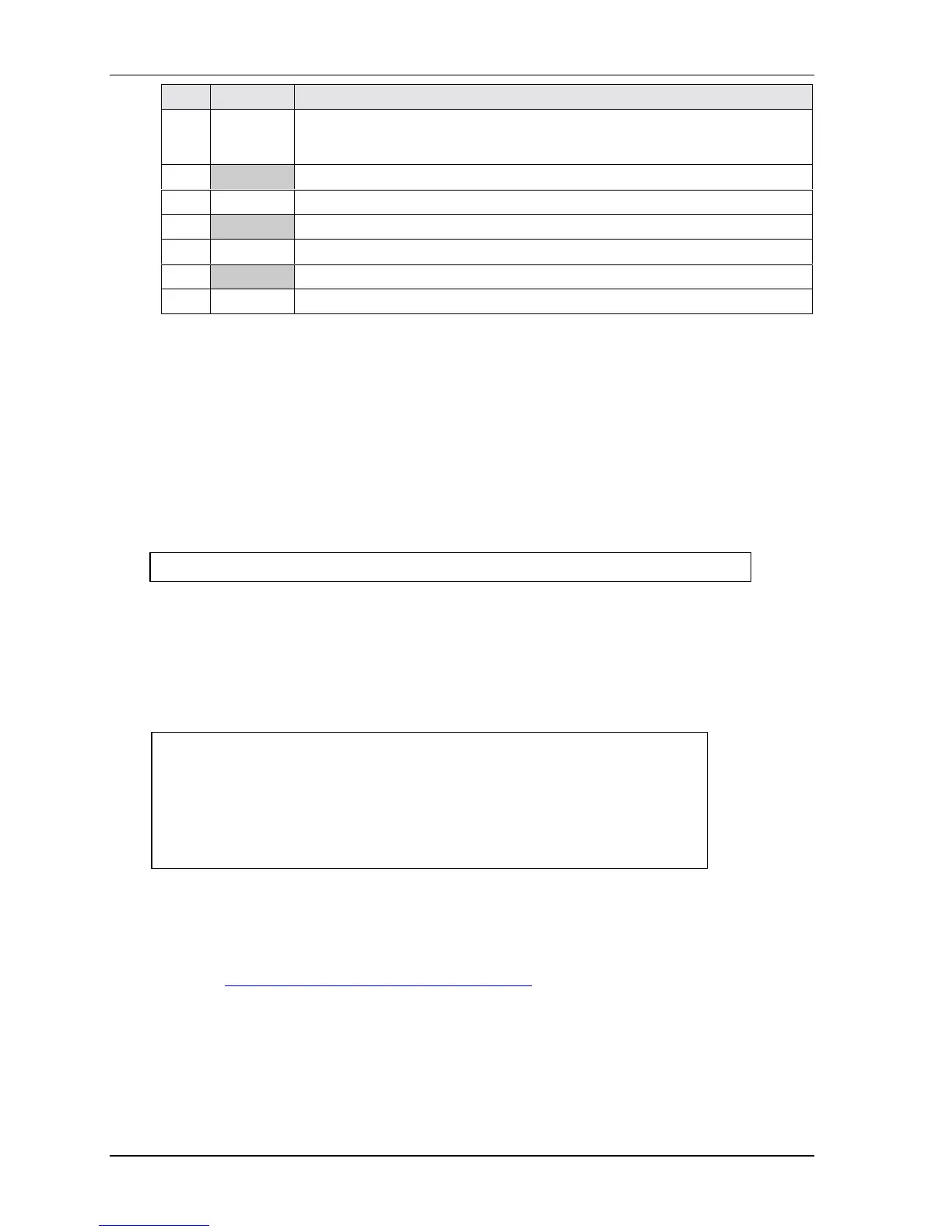
Pin # Signal Description
38
VSYNC Vertical Sync – This signal is used for the digital vertical sync output to the
CRT. Also used (with HSYNC) to signal power management state information
to the CRT per the VESA DPMS standard.
39
AGNDR Analog Ground for Red
40
RED Red – This pin provides the Red analog output to the CRT.
41
AGNDG Analog Ground for Green
42
GREEN Green – This pin provides the Green analog output to the CRT.
43
AGNDB Analog Ground for Blue
44
BLUE Blue – This pin provides the Blue analog output to the CRT.
Notes: The shaded area denotes power or ground. The signals marked with * indicate active low.
Miscellaneous
Real Time Clock (RTC)
The CoreModule 420 contains a Real Time (time of day) Clock (RTC), which can be backed up with a
Lithium Battery. The CoreModule 420 will function without a battery in those environments, which
prohibit inclusion of batteries. The CoreModule 420 will also continue to operate after the battery life
has been exceeded. Under these conditions all setup information is restored from the onboard Flash
memory during POST along with the default date and time information.
NOTE Some operating systems require a valid default date and time to function.
User GPIO Signals
The CoreModule 420 provides GPIO pins for customer use and the signals are routed to connector J8.
An example of how to use the GPIO pins is provided in the Miscellaneous Source Code Examples
subdirectory, under the CoreModule 420 Software menu on the CoreModule 420 Doc & SW CD-ROM
(cm420\software\examples\GPIO).
CAUTION To prevent a system crash, or render the CoreModule 420 BIOS
unusable, do not attempt to use the master GPIO pins (GPIOs 0-7).
The STPC Atlas processor has two GPIO blocks, master and slave.
The slave GPIO pins are reserved for customer applications. The
master GPIO pins are dedicated for BIOS use to control on-board
peripherals. The master GPIO pins can not be used for customer
applications.
The example program can be built by using the make.bat file. This produces a 16-bit DOS executable
application, gpio.exe, which can be run on the CoreModule 420 to demonstrate the use of GPIO pins.
For more information about the GPIO pin operation, refer to the Programming Manual for the STPC
Atlas processor at:
http://www.stmcu.com/devicedocs-Atlas-75.html