Chapter 3 Hardware
34 Reference Manual CoreModule 420
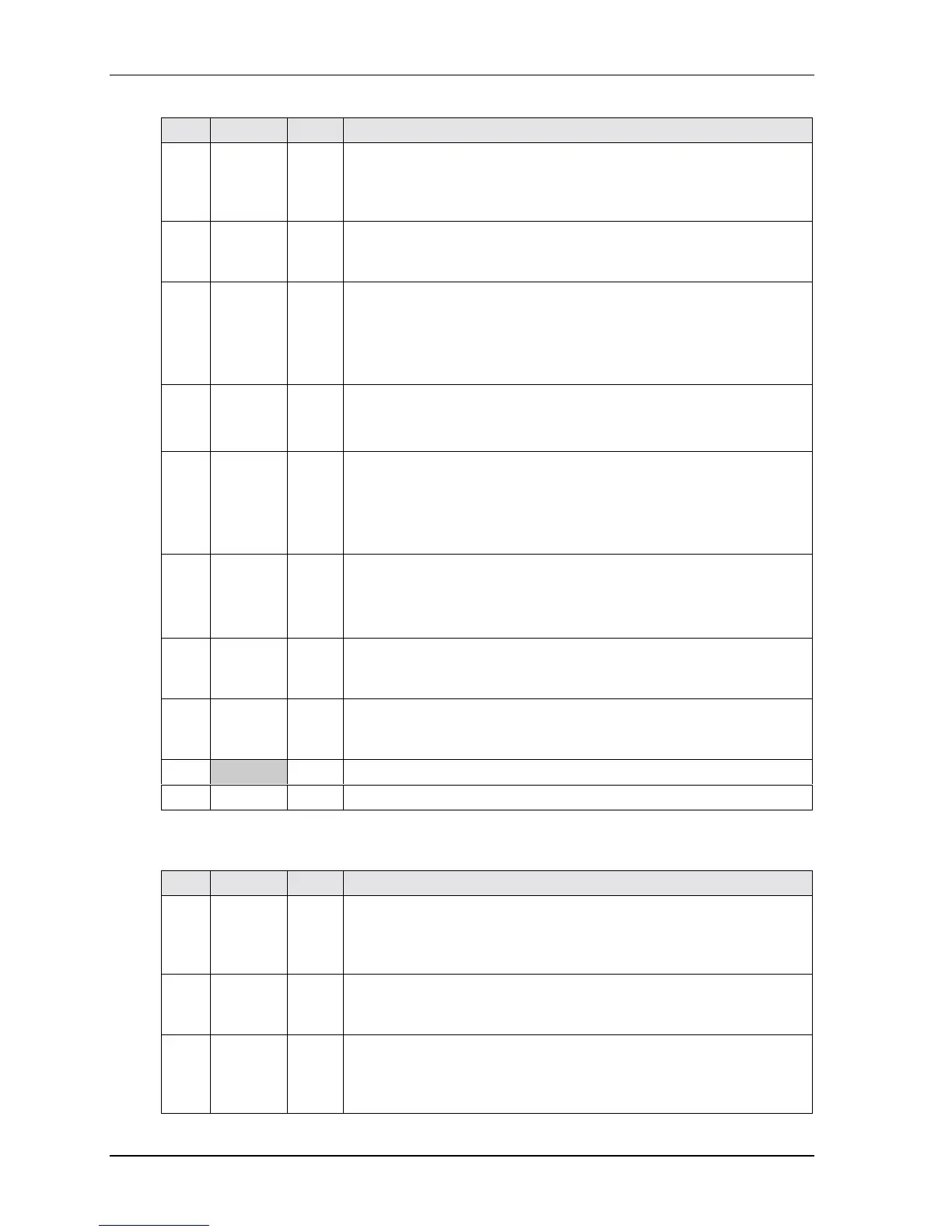
Table 3-12. Serial Ports Pin/Signal Descriptions (J3, J9)
Pin # Signal DB9 # Description
1DCD* 1
Data Carrier Detect – Indicator to the serial port that external modem is
detecting a carrier signal (i.e., a communication channel is currently
open). In direct connect environments, this input will be driven by DTR
as part of the DTR/DSR handshake.
2DSR* 6
Data Set Ready – Indicator to the serial port that external serial
communications device is powered, initialized, and ready. Used as
hardware handshake with DTR1 for overall readiness to communicate.
3
RXD
RX Data –
2
Receive Data – Serial port receive data input is typically held at a logic
1 (mark) when no data is being transmitted, and is held “Off” for a brief
interval after an “On” to “Off” transition on the RTS line to allow the
transmission to complete.
Serial Port 1 or 2 – If in RS485 mode, this pin is RX Data –.
4RTS*
Tx Data +
7 Request To Send – Indicates serial port is ready to transmit data. Used
as hardware handshake with CTS for low level flow control.
Serial Port 1 or 2 – If in RS485 mode, this pin is TX Data +.
5
TXD
Tx Data –
3
Transmit Data – Serial port transmit data output is typically held to a
logic 1 when no data is being sent. Typically, a logic 0 (On) must be
present on RTS, CTS, DSR, and DTR before data can be transmitted on
this line.
Serial Port 1 or 2 – If in RS485 mode, this pin is TX Data –.
6
CTS*
Rx Data +
8
Clear To Send – Indicator to the serial port that external serial
communication device is ready to receive data. Used as hardware
handshake with RTS for low level flow control.
Serial Port 1 or 2 – If in RS485 mode, this pin is RX Data +.
7 DTR* 4 Data Terminal Ready – Indicates serial port is powered, initialized, and
ready. Used as hardware handshake with DSR for overall readiness to
communicate.
8 RI* 9 Ring Indicator – Indicator to serial port that external modem is detecting
a ring condition. Used by software to initiate operations to answer and
open the communications channel.
9 GND 5 Digital Ground
10 KEY/NC NC Key Pin/Not connected
Notes: The shaded area denotes power or ground. The signals marked with * indicate active low.
Table 3-13. Serial 3 & 4 Interface Pins/Signals (J13, J14)
Pin # Signal DB9 # Description
1DCD* 1
Data Carrier Detect – Indicator to serial port that external modem is
detecting a carrier signal (i.e., a communication channel is currently
open). In direct connect environments, this input will be driven by DTR
as part of the DTR/DSR handshake.
2 DSR* 6 Data Set Ready – Indicator to serial port that external serial
communications device is powered, initialized, and ready. Used as
hardware handshake with DTR for overall readiness to communicate.
3 RXD 2 Receive Data – Serial port receive data input is typically held at a logic
1 (mark) when no data is being transmitted, and is held “Off” for a brief
interval after an “On” to “Off” transition on the RTS line to allow the
transmission to complete.