User Guide EVAL-ADE9113
EVALUATION BOARD SOFTWARE
analog.com Rev. 0 | 10 of 18
HARDWARE SETUP
Before running the software, the three boards must be connected
and the jumpers must be configured as follows:
1. Connect the SDP-B adapter (P6) to the EVAL-ADE9113EBZ
(P7) via the 26-pin connector.
2. Connect the SDP-B (J2) to the SDP-B adapter (P1) using the
120-pin connector. See Figure 13 for reference.
3. For the SDP-B adapter and the EVAL-ADE9113EBZ, the jumper
configuration selects the communication mode: daisy chain SPI
or direct SPI. Refer to Table 1, Table 2, Figure 11, and Figure 12
to install the jumpers accordingly.
Table 1. Jumper Configuration for SDP-B Adapter
Header
Jumper Position
Daisy-Chain SPI Direct SPI
P2 Pin 1 to Pin 2 Pin 1 to Pin 2
P3, P5 Open Open
P4, P7 Pin 1 to Pin 2 Pin 1 to Pin 2
P8 to P11 Pin 2 to Pin 3 Pin 1 to Pin 2
Table 2. Jumper Configuration for EVAL-ADE9113EBZ
Header
Jumper Position
Daisy-Chain SPI Direct SPI
P1 Pin 1 to Pin 2 Pin 1 to Pin 2
Pin 3 to Pin 5 Pin 3 to Pin 4
Pin 7 to Pin 9 Pin 5 to Pin 6
Pin 11 to Pin 13 Pin 7 to Pin 8
Pin 15 Pin 16 Pin 9 to Pin 10
Pin 11 to Pin 12
Pin 13 to Pin 14
Pin 15 to Pin 16
P4, P5, P6 Pin 1 to Pin 2 Pin 2 to Pin 3
Figure 11. Jumper Configuration for Daisy-Chain SPI
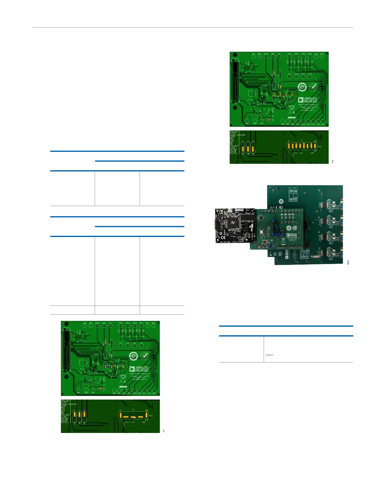
Figure 12. Jumper Configuration for Direct SPI
Figure 13. EVAL-ADE9113KTZ Hardware Setup for Daisy-Chain SPI
4. Use the USB cable to connect the SDP-B to the PC. The
POWER LED on the SDP-B, and the VDDLED and IRQA on
the SDP-B adapter, must turn green immediately. After a few
seconds, the IRQB, IRQC, and IRQN LEDs turn on also. See
Table 3 for a description of what these LEDs mean.
Table 3. LED Description
Name Meaning When On
POWER Power supplied to SDP-B
VDDLED Power supplied to SDP-B adapter
IRQx IRQ pin of the ADE9113 on Phase x is low