User Guide EVAL-ADE9113
EVALUATION BOARD HARDWARE
analog.com Rev. 0 | 7 of 18
SETTING UP THE EVAL-ADE9113EBZ AS AN
ENERGY METER
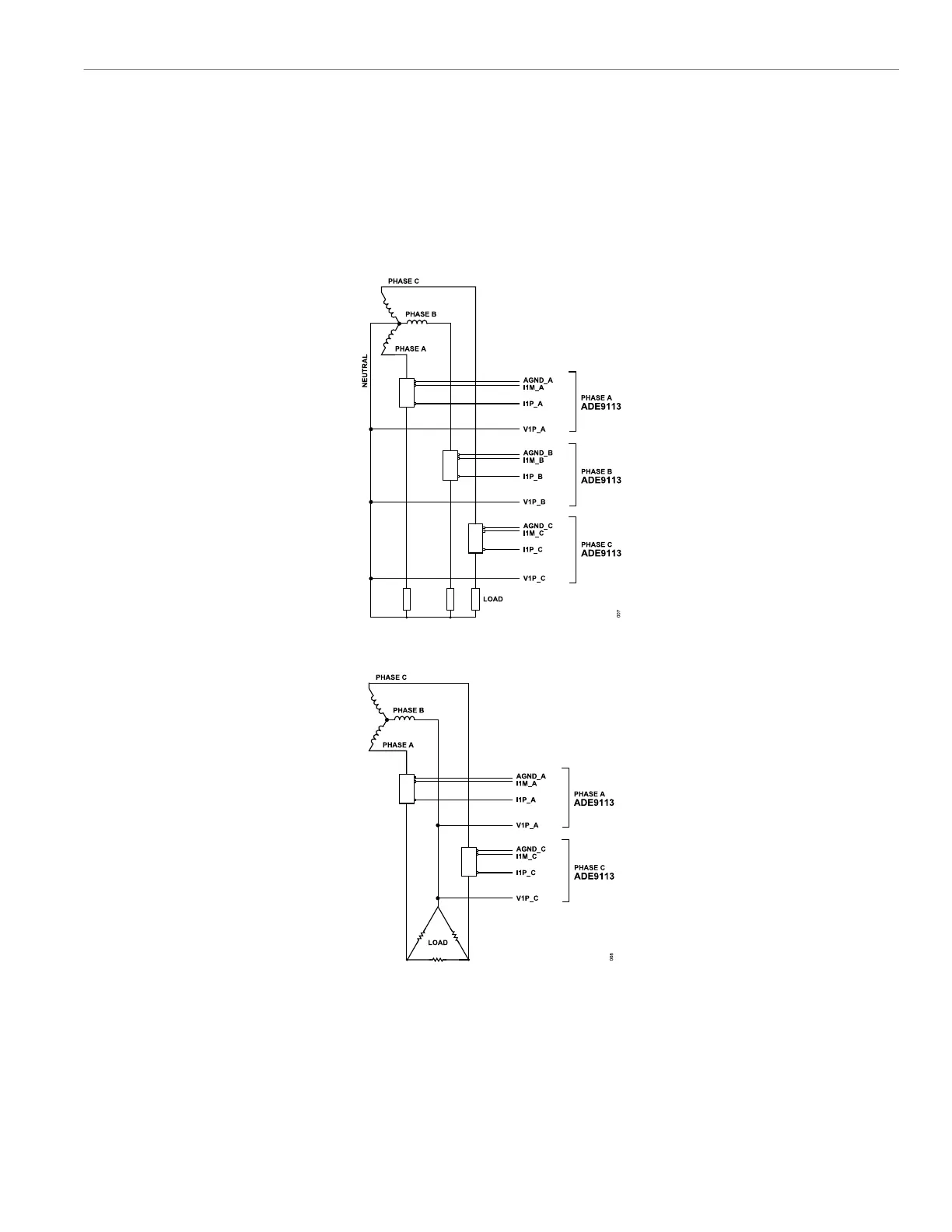
Figure 7 shows a typical setup for the EVAL-ADE9113EBZ. In this
example, an energy meter for a 3-phase, 4-wire wye distribution
system is shown. Shunts are used to sense the phase currents
and are connected as shown in Figure 7. The line voltages are
connected directly to the EVAL-ADE9113EBZ as shown. The EVAL-
ADE9113EBZ is supplied from one power supply provided by the
PC through the USB cable.
Figure 8 shows a setup for the EVAL-ADE9113EBZ as an energy
meter for a 3-phase, 3-wire, delta distribution system. The Phase
B voltage is considered as a reference, and the V1P_x test pins of
Phase A and Phase C of the ADCs on the ADE9113 are connected
to it.
Figure 7. Typical Setup for the EVAL-ADE9113EBZ for 3-Phase, 4-Wire, Wye Distribution System
Figure 8. Typical Setup for the EVAL-ADE9113EBZ for 3-Phase, 3-Wire Delta Distribution Systems