User Guide EVAL-ADE9113
EVALUATION BOARD HARDWARE
analog.com Rev. 0 | 4 of 18
OVERVIEW
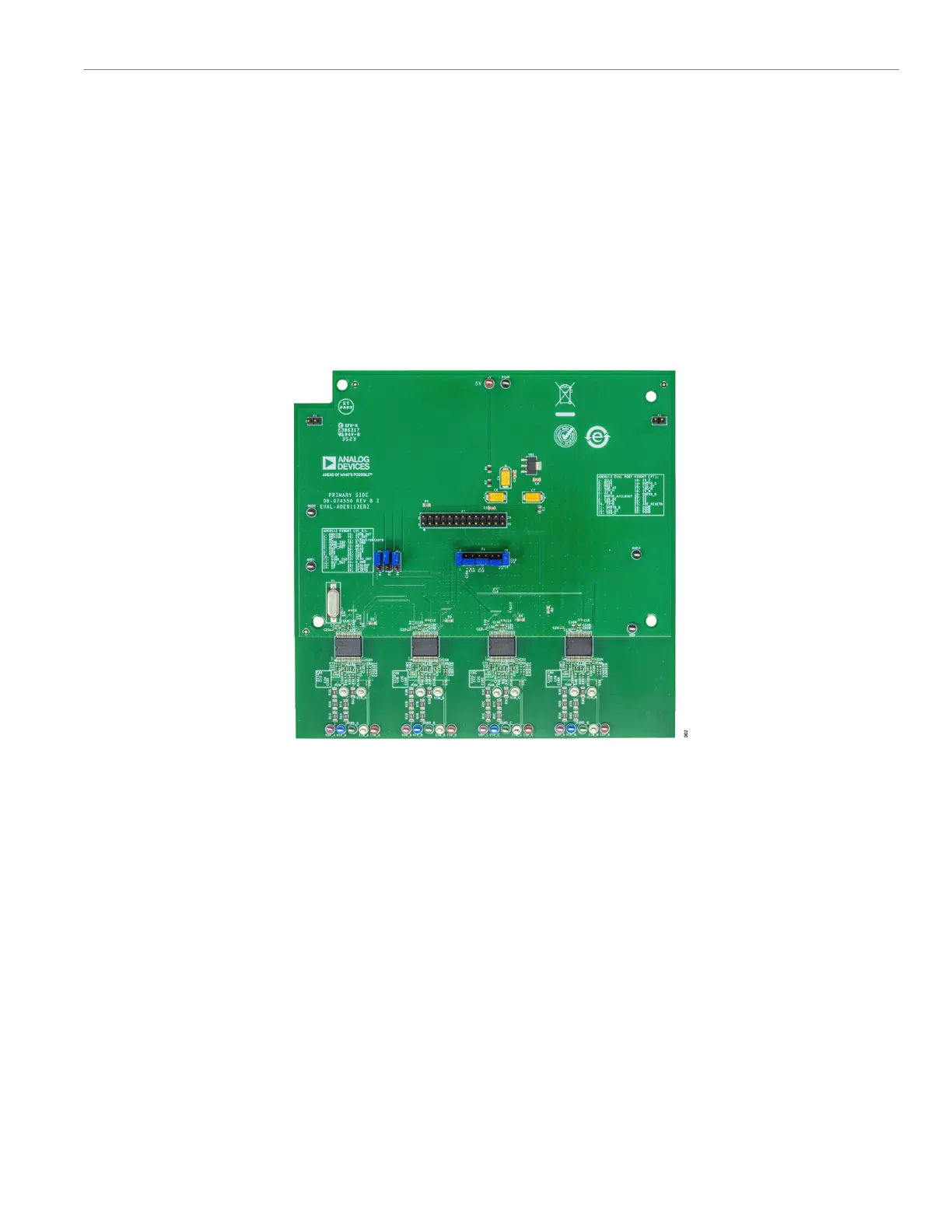
To evaluate the ADE9113, three boards are connected together
(see Figure 1). The EVAL-ADE9113EBZ, which is populated with
four ADE9113 ADCs, can be used as an implementation example
of a 3-phase energy meter (see Figure 2).
The SDP-B adapter board and MCU adapter board are both provid-
ed in the evaluation kit. The 26-pin connector, P6, on the SDP-B
adapter board, or P6 on the MCU adapter board is connected to the
P7 connector on the EVAL-ADE9113EBZ evaluation board.
The SDP-B adapter board is connected to the SDP-B Blackfin
board (also referred to as SDP-B or EVAL-SDP-CB1Z) using a 120-
pin connector. The EVAL-SDP-CB1Z must be ordered separately
when ordering the EVAL-ADE9113KTZ; the kit and the SDP-B
board are purchased and packaged separately but must be used
together. Alternatively, the MCU adapter board is connected to
an off-the-shelf microcontroller board through the Arduino type
connectors, P1, P2, P3, P4, and P5. This microcontroller board is
not provided; however, it can aid in the development of firmware on
the system of choice.
The SDP-B Blackfin board consists of an ADSP-BF527 microcon-
troller that handles all the communications from the PC to the
ADE9113 devices populating the evaluation board (see Figure 3).
Figure 2. EVAL-ADE9113EBZ Evaluation Board