www.analog.com
Analog Devices
│
18
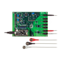
MAX30001 Evaluation System Evaluates: MAX30001
MAX30002
Detailed Description of Hardware
The MAX30001 EV system provides a single platform to
evaluate the functionality and features of the MAX30001
with Biopotential (ECG, R-to-R, and Pace Detection) and
Bioimpedance (BioZ) measurement capabilities. The
board contains jumpers and optional resistors and capacitors
to test the MAX30001 under several conditions. A list of
all jumpers and their respective functions is available in
Table 1. An onboard 32.768kHz crystal oscillator (U5)
supplies FCLK to the IC, but external frequency generation
is supported.
The EV system utilizes the MAX32630FTHR Cortex-M4F
Microcontroller for Wearables for interfacing with the
GUI and optionally providing power to the MAX30001.
The MAX32630FTHR operates either from a host PC
or directly from a Li+ battery. If an SD card is present in
the MAX32630FTHR, register settings and measurement
congurations can be saved through the GUI. When the
EV kit operates without a host PC, pressing SW2 on the
MAX32630FTHR initiates the measurement and saves
log les to the SD card. Logging is stoped by pressing
SW2 a second time.
Refer to Figure 17 for a simplied schematic of the EV kit
biopotential circuitry.
Table 1. Description Of Jumpers
JUMPER SHUNT POSITION DESCRIPTION
J_ECGN 1-2* Connects ECGN on the IC to C_ECGN on the EV kit.
J_ECGP 1-2* Connects ECGP on the IC to C_ECGP on the EV kit.
EN_BN 1-2 Connects ECGN to BIN.
EP_BP 1-2 Connects ECGP to BIP.
EN_UNBAL 1-2* Bypasses the ECG electrode unbalance on ECGN.
EP_UNBAL 1-2* Bypasses the ECG electrode unbalance on ECGP.
EP_EN 1-2 Short ECGP to ECGN.
J_BIN 1-2* Connects BIN on the IC to C_BIN on the EV kit.
J_BIP 1-2* Connects BIN on the IC to C_BIN on the EV kit.
RN 1-2* Connects one end of R28 to BIN.
RP 1-2* Connects one end of R28 to BIP.
DN_BN 1-2 Connects DRVN to BIN.
DP_BP 1-2 Connects DRVP to BIP.
BP_BN 1-2 Short BIP to BIN.
J_DRVN 1-2 Connects DRVN on the IC to C_DRVN on the EV kit.
J_DRVP 1-2 Connects DRVP on the IC to C_DRVP on the EV kit.
BB_SEL
1-2* Use VCM as the body bias.
2-3 Use an adjustable voltage from 0V to OVDD as the body bias. Adjust voltage with R7.
J_RBIAS 1-2* Connect an external 324kΩ resistor to RBIAS.
BUFF1_IN 1-2 Input to second buer of U4.
 Loading...